Sensor for an aerosol delivery device

a technology of aerosol and sensor, which is applied in the direction of inhalators, other medical devices, volume/mass flow by dynamic fluid flow effect, etc., can solve the problem of not being able to provide indication of any particular properties of airflow, and achieve the effect of improving the output consistency of the device, improving the user experience of the device, and increasing the heating of the heating member

Active Publication Date: 2015-10-08
RAI STRATEGIC HLDG INC
View PDF7 Cites 164 Cited by
  • Summary
  • Abstract
  • Description
  • Claims
  • Application Information

AI Technical Summary

Benefits of technology

[0007]A sensor utilized in an aerosol delivery device according to the present disclosure, however, can be configured to detect specific properties of the airflow through an aerosol delivery device and output a signal across a continuous range that varies in relation to the property of the airflow measured. For example, the output signal can relate information regarding the rate of airflow, which may correspond to the intensity of the draw on the device by a user, and the device can include control elements configured to utilize the output signal from the sensor to active the heater in a defined manner relative to the output signal. In other words, in some embodiments, as airflow rate through the aerosol delivery device increases, the electrical current delivered to a heating member may increase and thus increase heating by the heating member. Similar relative changes in operation may be controlled in relation to one or more further functional elements of the aerosol delivery device. In this manner, an aerosol delivery device may be configured to provide for adaptive functioning and thus improve output consistency of the device or otherwise improve a user experience with the device.

Problems solved by technology

Although known aerosol delivery devices may include a sensor for detecting draw on the device, such known sensors are configured to provide a “trigger” signal that is generated upon reaching a threshold and that does not provide a variable output.
While such sensor may be suitable to detect the presence of airflow at a threshold and output an on / off signal similar to a switch, such sensor cannot provide indication of any particular properties of the airflow, such as strength of the airflow, more particularly the airflow rate, volume, or the like.

Method used


Image

  • Sensor for an aerosol delivery device
  • Sensor for an aerosol delivery device
  • Sensor for an aerosol delivery device

Examples


Embodiment Construction

[0023]The present disclosure will now be described more fully hereinafter with reference to exemplary embodiments thereof. These exemplary embodiments are described so that this disclosure will be thorough and complete, and will fully convey the scope of the disclosure to those skilled in the art. Indeed, the disclosure may be embodied in many different forms and should not be construed as limited to the embodiments set forth herein; rather, these embodiments are provided so that this disclosure will satisfy applicable legal requirements. As used in the specification, and in the appended claims, the singular forms “a”, “an”, “the”, include plural referents unless the context clearly dictates otherwise.

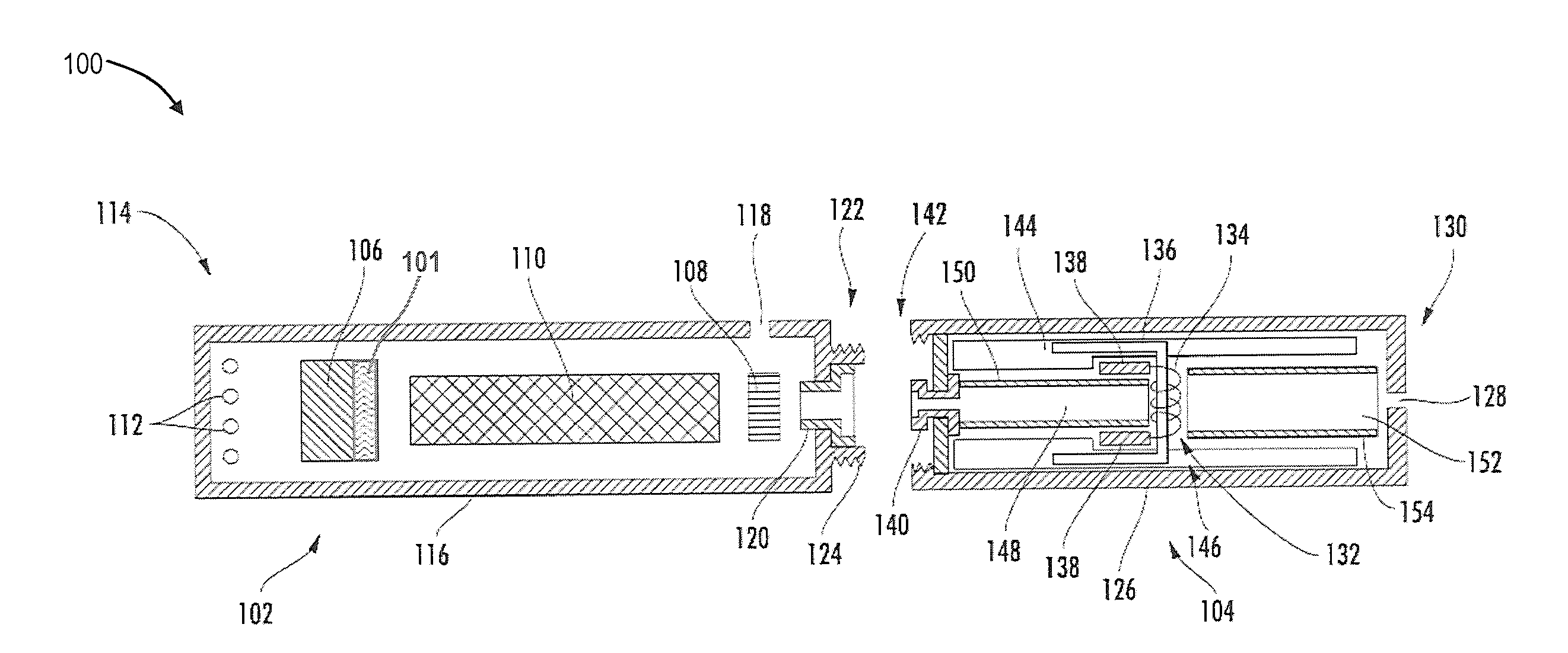
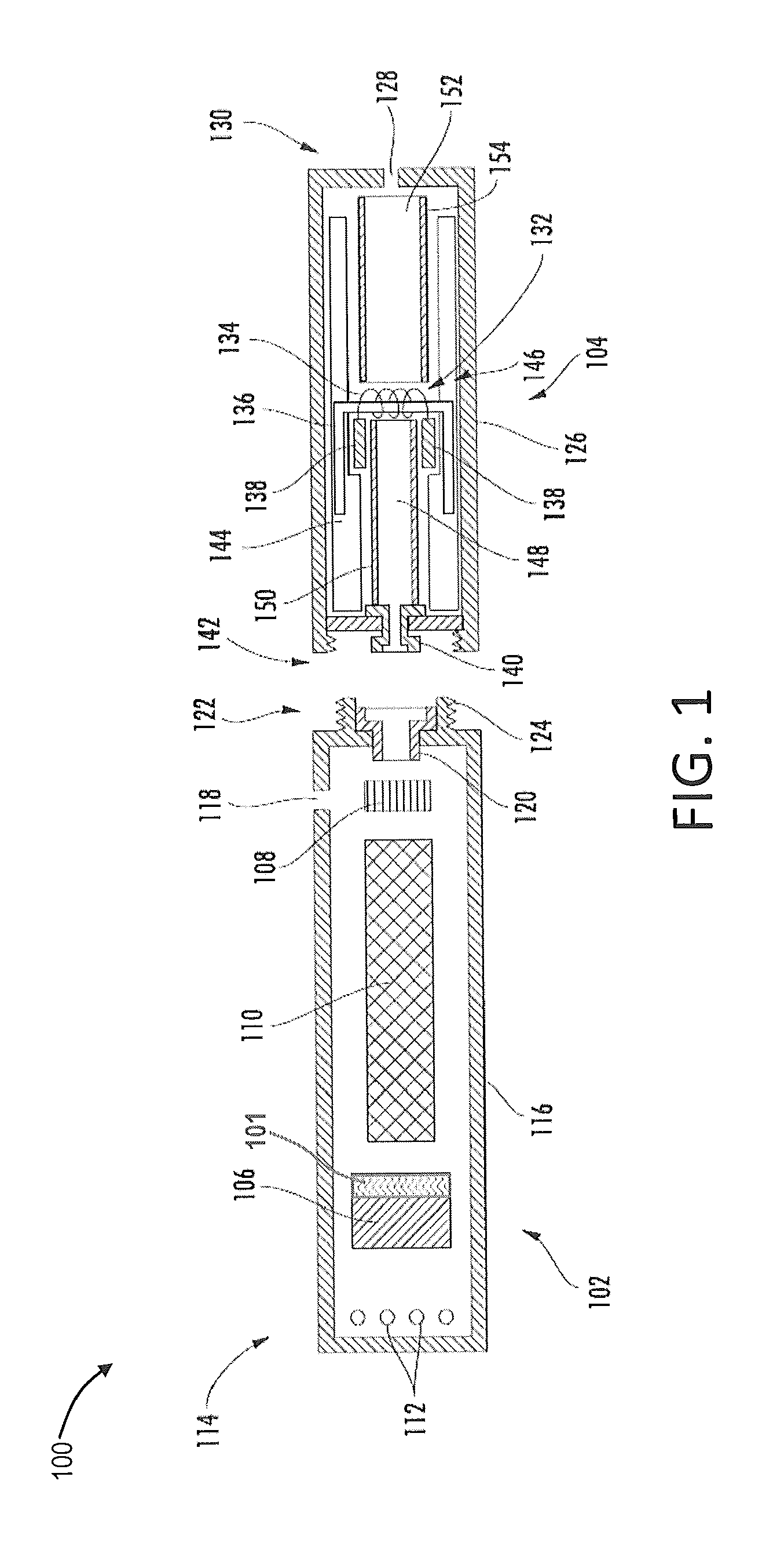
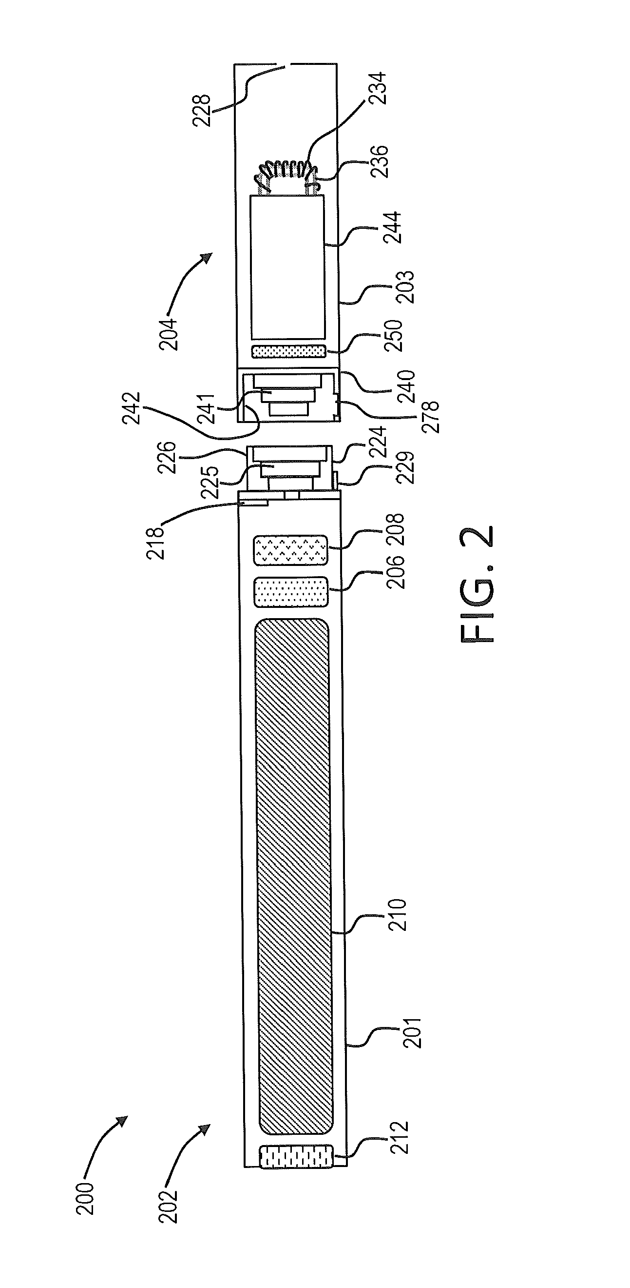
[0024]The present disclosure provides descriptions of aerosol delivery devices or smoking articles, such as so-called “e-cigarettes.” It should be understood that the mechanisms, components, features, and methods may be embodied in many different forms and associated with a variety of ...


PUM


Abstract

The present disclosure relates to an aerosol delivery device including a variable output flow sensor. The variable output flow sensor particularly can be a flex/bend sensor wherein output from the sensor varies based upon changes in electrical current flow (e.g., resistance) along an extension of the sensor relative to flexing or bending of the extension resulting from airflow across the extension. The disclosure further provides methods for controlling operation of an aerosol delivery device through utilization of a variable output flow sensor. In particular, control of functional elements (e.g., a heating member, a fluid delivery member, and a sensory feedback member) can allow for real-time changes in the operation of the aerosol delivery device relative to airflow through the device.

Description

FIELD OF THE DISCLOSURE[0001]The present disclosure relates to aerosol delivery devices such as smoking articles. The aerosol delivery device may be configured to heat a material, which may be made or derived from tobacco or otherwise incorporate tobacco, to form an inhalable substance for human consumption. The aerosol delivery device particularly can incorporate a variable output sensor.BACKGROUND[0002]Many smoking devices have been proposed through the years as improvements upon, or alternatives to, smoking products that require combusting tobacco for use. Many of those devices purportedly have been designed to provide the sensations associated with cigarette, cigar, or pipe smoking, but without delivering considerable quantities of incomplete combustion and pyrolysis products that result from the burning of tobacco. To this end, there have been proposed numerous smoking products, flavor generators, and medicinal inhalers that utilize electrical energy to vaporize or heat a volat...

Claims


Application Information

Patent Timeline
Patent Type & Authority Applications(United States)
IPC IPC(8): A24F47/00A24F40/10A24F40/485A24F40/51A24F40/60
CPCA24F47/008A61M15/06G01F1/28A61M2205/3334A61M15/0091A61M2205/581A61M2205/583A61M2205/8206A61M11/042A24F40/60A24F40/10A24F40/485A24F40/51A24F40/50
Inventor HENRY, JR., RAYMOND CHARLES
Owner RAI STRATEGIC HLDG INC
Why Eureka
Try Eureka