
Drill Press with Pivotable Table

a technology of pivoting table and drill press, which is applied in the field of drill press, can solve the problem of not having a high-precision machine tool

Inactive Publication Date: 2015-10-08
CHANG LEE CHENG
View PDF33 Cites 7 Cited by
  • Summary
  • Abstract
  • Description
  • Claims
  • Application Information

AI Technical Summary

Benefits of technology

The present invention is a drill press with a pivotable table and a collar. The table can be moved relative to the support column and has various fixed and movable positions. The press has two work platforms that move relative to the support column when the pivot device moves. The technical effects of this invention include improved efficiency, flexibility, and precision in drilling and machining operations.

Problems solved by technology

However, it is not a high precision machine tool.

Method used


Image

  • Drill Press with Pivotable Table
  • Drill Press with Pivotable Table
  • Drill Press with Pivotable Table

Examples


Embodiment Construction

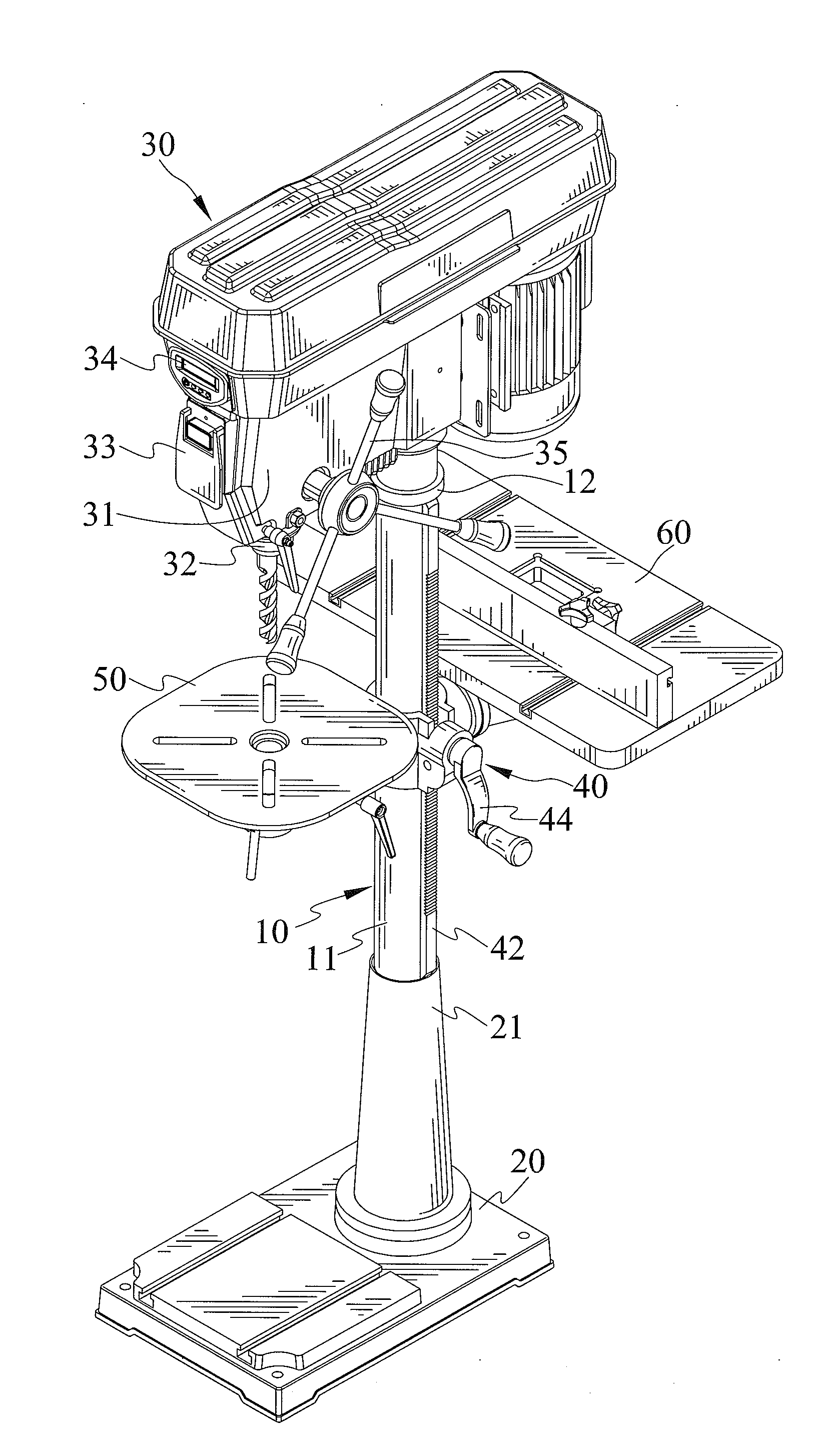
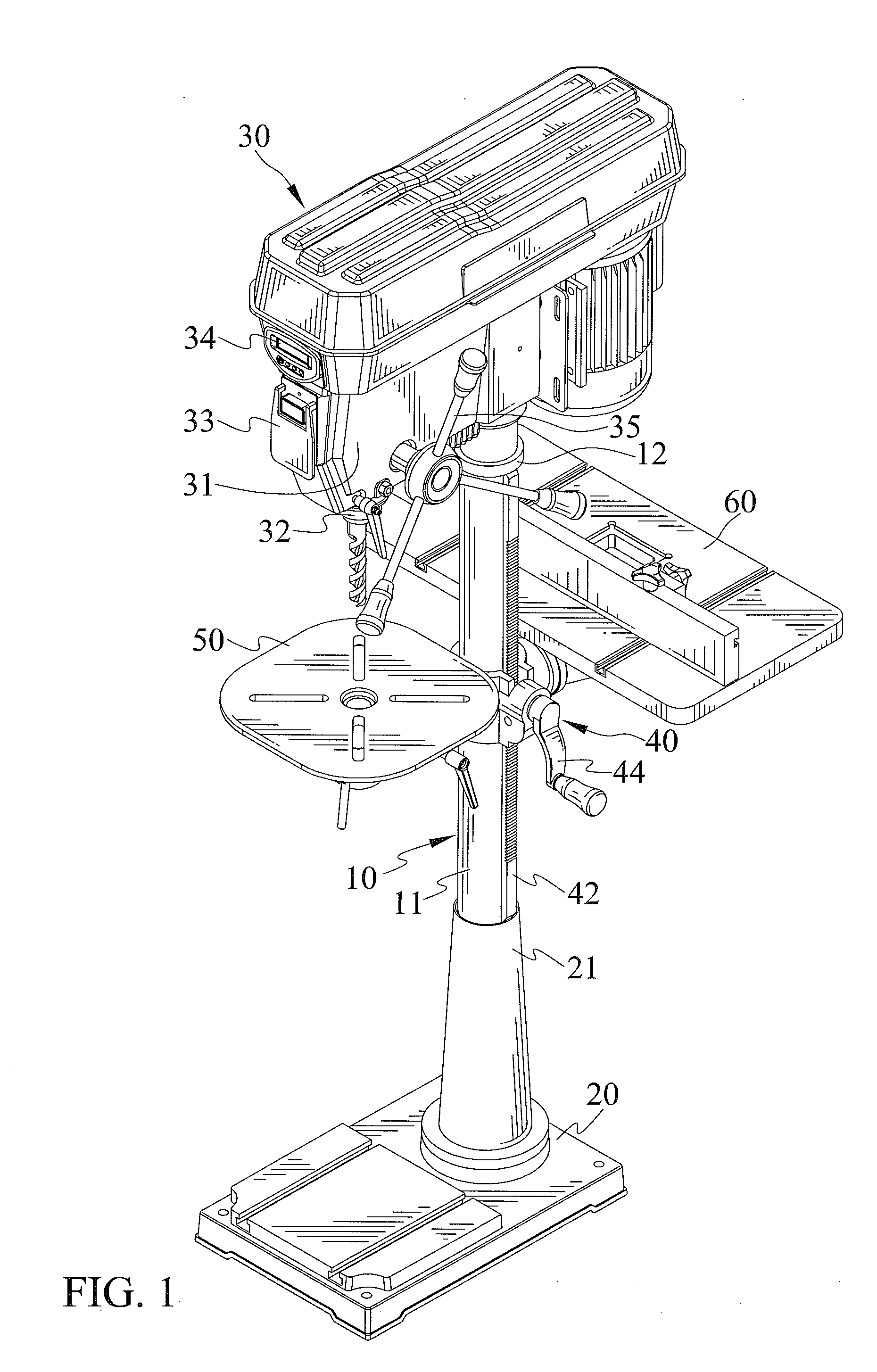
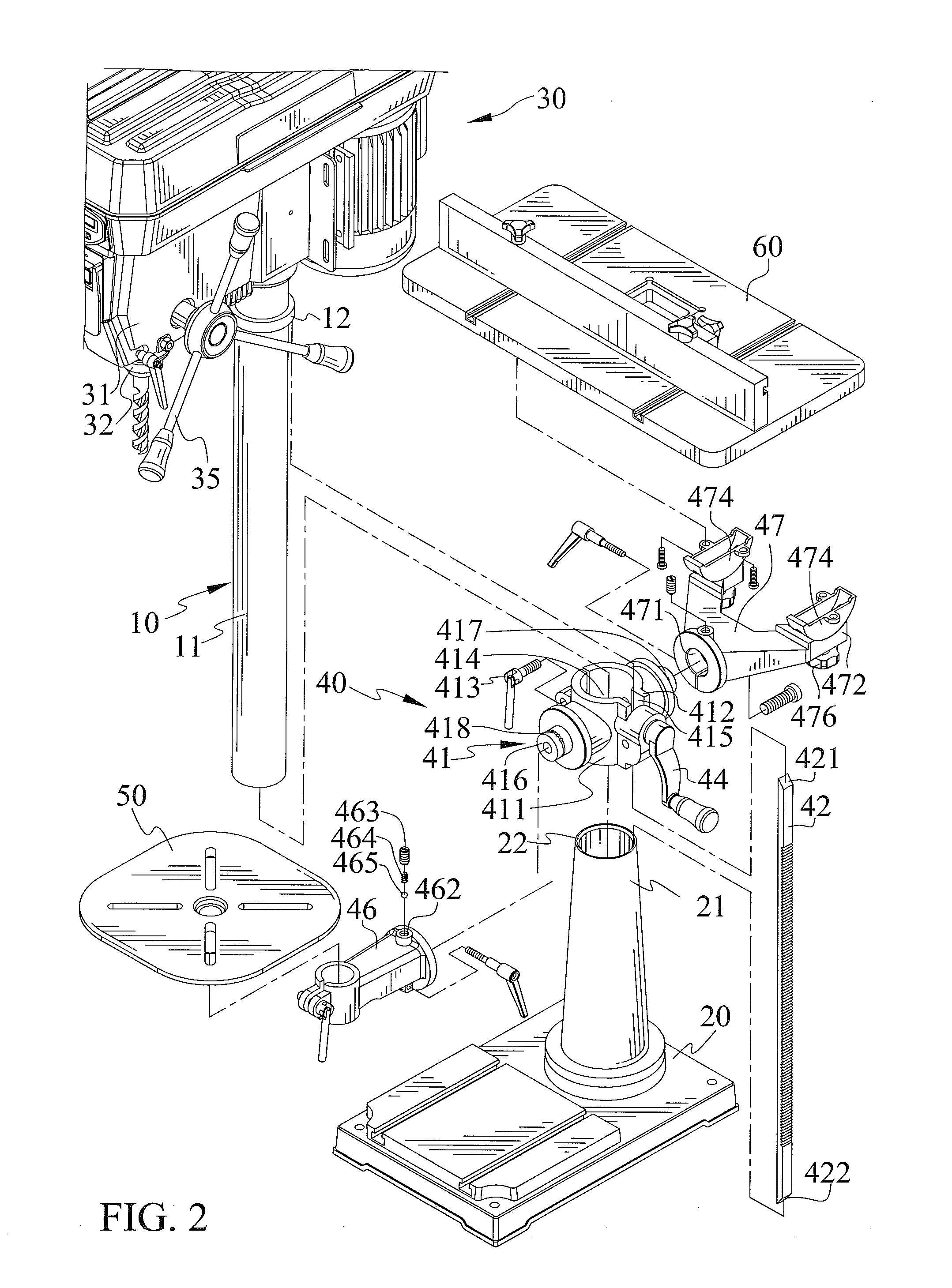
[0026]FIGS. 1 through 9 show a drill press with pivot table(s) in accordance with the present invention. The drill press includes a support column 10 and a collar 12 disposed on an outer periphery 11 of the support column 10. The outer periphery 11 of the support column 10 and the collar 12 delimit a first groove 13 therebetween;

[0027]A base 20 defines a fixing end 21 connecting to an end of the support column 10. The outer periphery 11 of the support column 10 and the base 20 delimi a second groove 22 therebetween.

[0028]A head 30 connects to another end of the support column 10 and includes a drive device 31 with a chuck 32. The drive device 31 is in a spin motion in the operation of the head 30.

[0029]The drill press has a turned on mode and a turned off mode. The drill press includes a switch 33 controlling the head 30. The drive device 31 includes a motor cooperating therewith. The switch 33 is connected with the motor. The motor can drive the drive device 31 to spin a tooling. T...


PUM

PropertyMeasurementUnit
Timeaaaaaaaaaa
Displacementaaaaaaaaaa

Abstract

A drill press with pivot table(s) includes a support column and a collar disposed on an outer periphery of the support column. The outer periphery of the support column and the collar delimit a first groove therebetween. A base connects to the support column. The outer periphery of the support column and the base delimit a second groove therebetween. A pivotal device is movable relative to the support column. The pivotal device has various fixed pivoting and sliding positions relative to the support column. A first work platform connects to the pivotal device. The first work platform is movable relative to the pivotal device. A second work platform connects to the pivotal device. The second work platform is movable relative to the pivotal device.

Description

BACKGROUND OF THE INVENTION[0001]1. Field of the Invention[0002]The present invention relates to a drill press and, particularly to a drill press with pivotal table(s).[0003]2. Description of the Related Art[0004]Generally, a machine tool is a kind of machinery for cutting workpieces or processing machine parts. When processing a workpiece, the cutting machine includes a tooling equipped thereto moving relative to the workpiece, with a first relative movement being classified as a main movement, with a second relative movement being classified as a feed movement. A user can use the machine tool to form, cut, or connect. Different machine tools include lathes, milling machines, grinding machines, and drilling machines.[0005]A conventional drill press is a machine tool which includes a drill head for drilling a hole on a workpiece. The drill head is set to turn, and this is a main movement of the drill head. The drill head can be axially fed. The drill press has a simple structure. Ho...

Claims


Application Information

Patent Timeline
IPC IPC(8): B23B39/00B23Q17/22B23B47/00
CPCB23B39/00B23B47/00Y10T408/5617Y10T408/21Y10T408/5614B23Q17/22
Inventor CHANG, LEE-CHENG
Owner CHANG LEE CHENG
Learn More