

Card Body with Variable Film Layers
- Summary
- Abstract
- Description
- Claims
- Application Information
AI Technical Summary
Benefits of technology
Problems solved by technology
Method used
Image

Examples
first embodiment
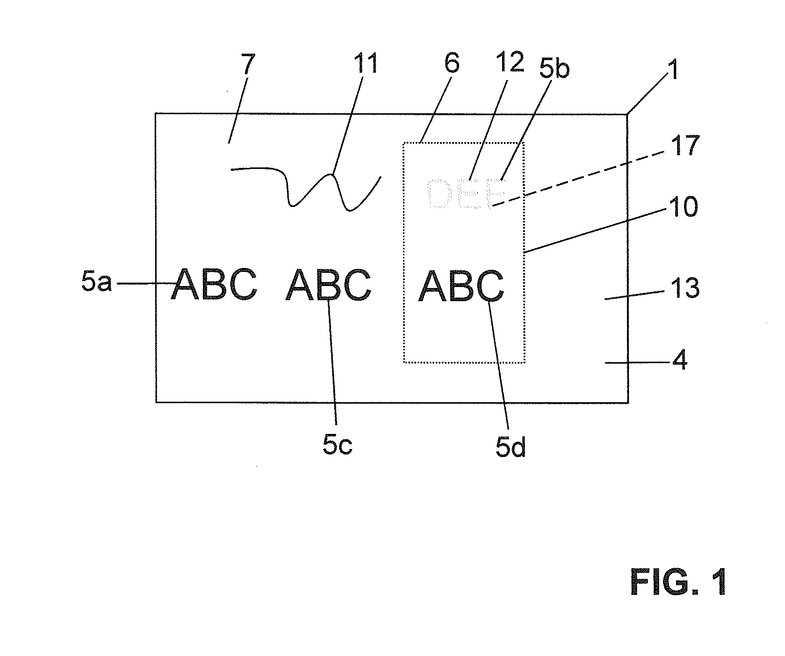
[0058] which is shown in FIG. 4, the step of modification comprises a placement of at least one film part 10 absorbing light of the first wavelength λ1 onto the upper side 13 of the information layer 4. Then, the film part 10 is connected, in particular fused or adhesively bonded, to the base layer 2 and the information layer 4 during a connection step. Particularly preferably, the connecting is laminated by laminating film part, base layer 2 and information layer 4 together.
[0059]The at least one film part 10 is arranged on the information layer 4 in relation to the base layer 2 during the modification step, wherein the film part 10 is in planar contact with the information layer 4 prior to the connecting, in particular the laminating.
[0060]During the connection by way of lamination, the film part 10 is introduced into the information layer 4. The upper side 19 of the film part 10 then lies flush with the upper side 13 of the information layer such that the information layer 4 or t...
second embodiment
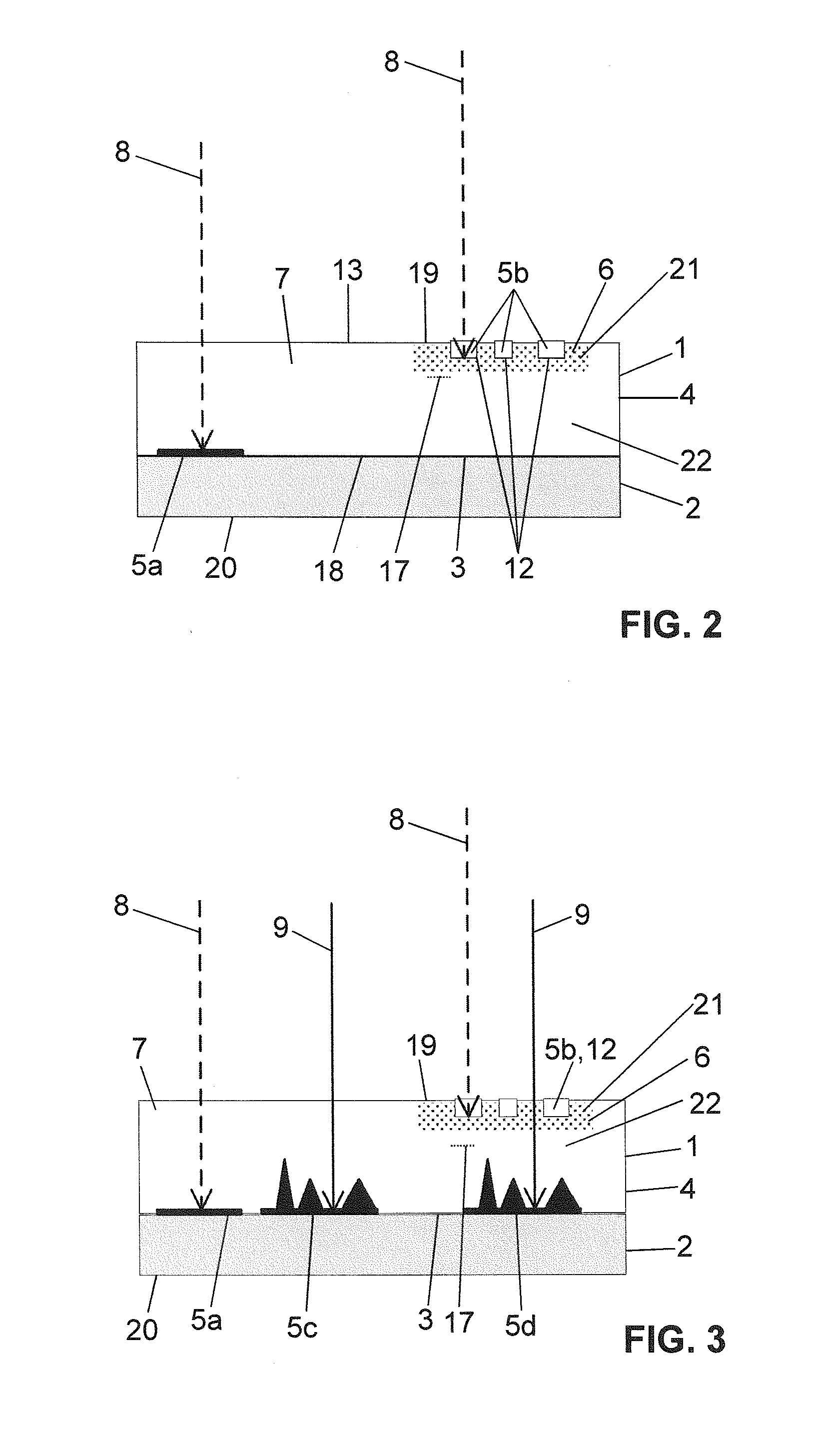
[0062] which is shown in FIG. 5, the modification step comprises an insertion of a film part 10 which absorbs light of the first wavelength λ1 into a cavity 16 in the information layer 4, which film part 10 is then connected, in particular fused or adhesively bonded, to the base layer 2 and the information layer 4 during a connection step. Particularly preferably, film part, base layer 2 and information layer 4 are laminated together.
[0063]By way of example, as shown in FIG. 5, the cavity can be formed by a cutout in a first film layer 14 of the information layer 4, said first film layer then resting on a second film layer 15. These two film layers 14, 15 are then connected together, in particular laminated, to form the information layer 4. The above-described further layer 22 is then provided by the film layer 14.
[0064]In this case, the second film layer 15 extends over the whole base layer and constitutes the information layer under the film part 6 in the connected state. However,...
PUM
| Property | Measurement | Unit |
|---|---|---|
| Wavelength | aaaaa | aaaaa |
| Wavelength | aaaaa | aaaaa |
| Wavelength | aaaaa | aaaaa |
Abstract
Description
Claims
Application Information