
Monitoring shots of firearms

Inactive Publication Date: 2015-10-08
C4 INTEGRATED SOLUTIONS LLC
View PDF2 Cites 44 Cited by
  • Summary
  • Abstract
  • Description
  • Claims
  • Application Information

AI Technical Summary

Benefits of technology

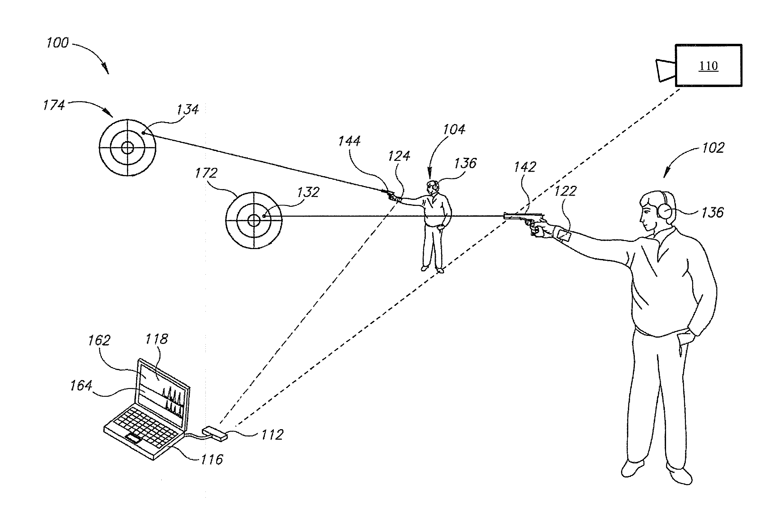
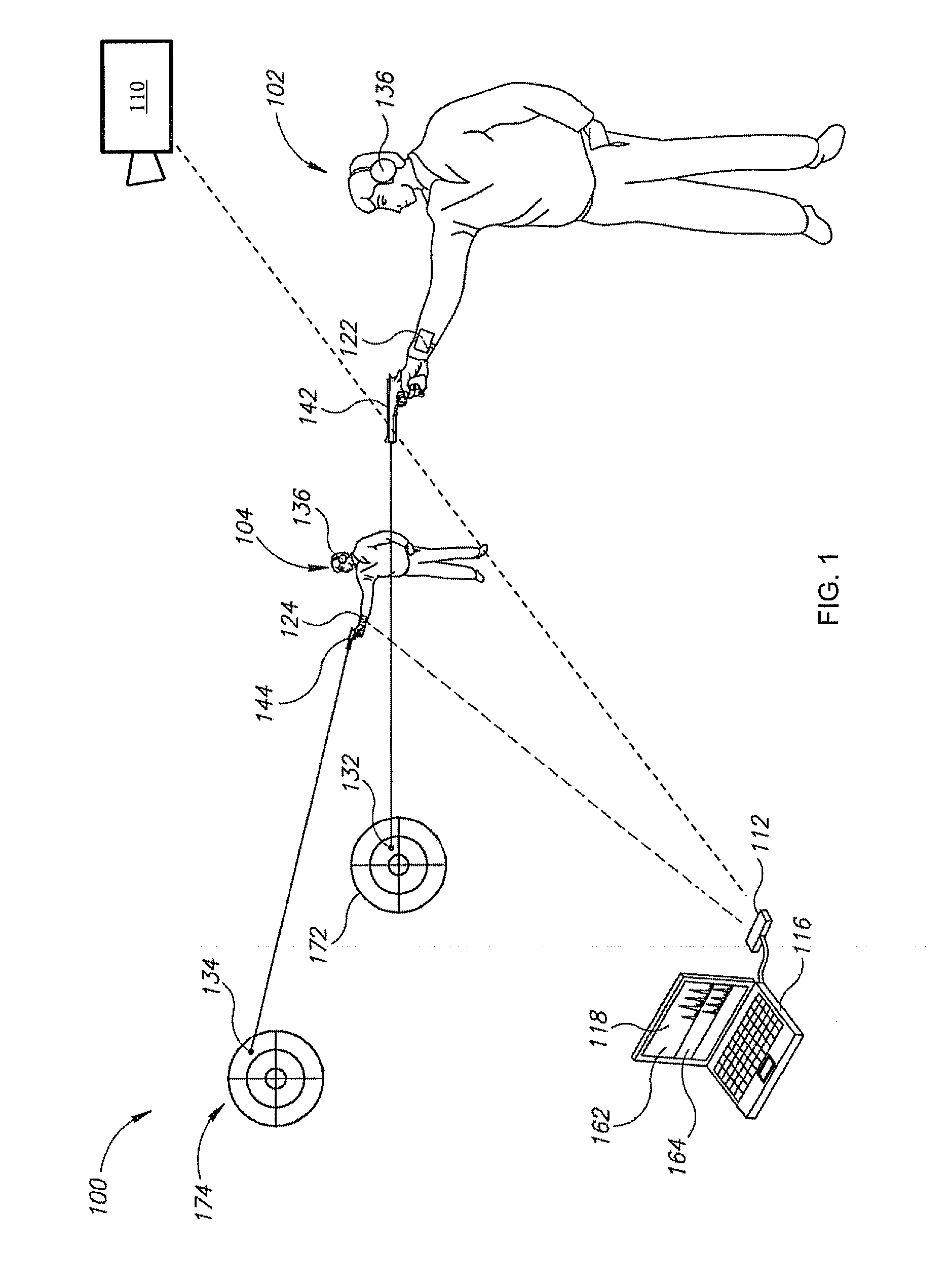
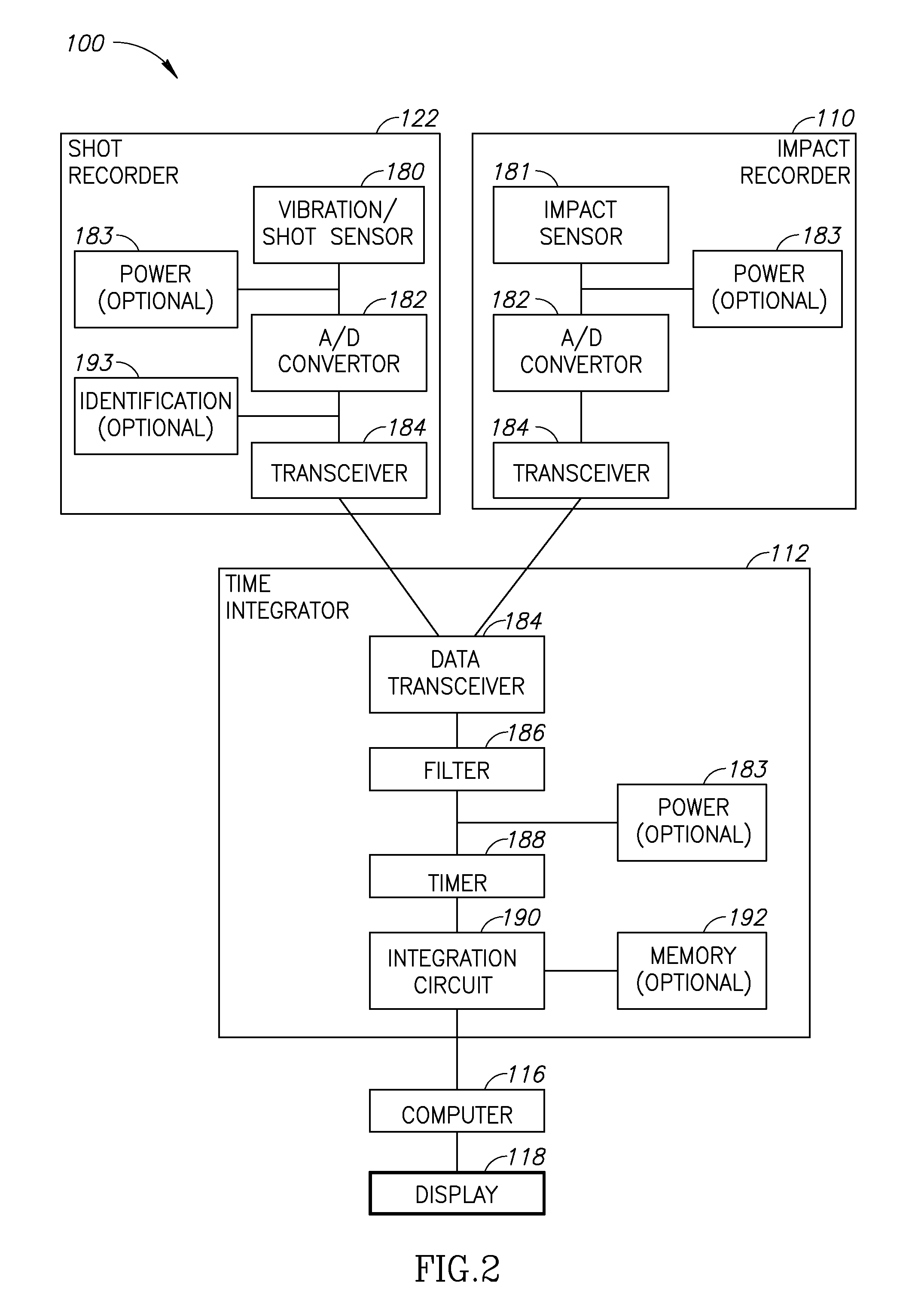
The present invention provides a device and system for monitoring shots fired by a specific user. The monitoring device includes an identification module to store an exclusive identification for the user, a memory module, a wireless communications module, and a motion sensor to sense data about the user's movements. The processor receives data from the motion sensor and analyzes it to identify typical movement patterns before, during, and after firing to identify the user as the shooter. The device can also include a processing module to at least partially process data before providing it to the processor, attachment straps to attach the device to a wrist, a physiological sensor to monitor physiological measures, an audio sensor to detect sounds, and an impact recorder to detect impacts of shots. The system may also include multiple monitoring devices and a timer to process data from the devices and impact recorders in parallel.

Problems solved by technology

However, in many kinds of weapons, such as rifles, the intensity of pressure on the handle cannot predict the firing quality.
However, this method of assessment provides poor prediction of the quality and / or success of the shooting, for example, of the ability to hit the target.
Additionally, such method is not very reliable for detection and identification of the deferent types of shooter's movements before, during and after the firing.
These methods are not suitable for simultaneous management of the entire shooting arena.
Additionally, these methods may require several devices to be installed on the weapons, which may limit and alter significantly the natural movements of a shooter.
For example, known methods use a communication and / or power cable to connect the weapon to a computer, thus limiting the natural movement of the shooter.
All these devices on the weapon may make these known methods very inconvenient and limiting and decrease the usability of these known methods for realistic simulations.

Method used


Image

  • Monitoring shots of firearms
  • Monitoring shots of firearms
  • Monitoring shots of firearms

Examples


Embodiment Construction

[0033]Prior to setting forth the detailed description, it may be helpful to set forth definitions of certain terms that will be used hereinafter.

[0034]As used herein, the term “shooting range” encompasses firing ranges, target ranges, shooting training, smart shooting range or other weapons training or testing environments or configurations.

[0035]As used herein, the phrases “multiple user shooting ranges”, “multiple user shooting areas”, or similar phrases refer to areas in which there are multiple shooters users shooting in areas in which there is firing range management.

[0036]As used herein, the phrase “firing range management” refers to, inter alia, group shooting; multi-user shooting; time-challenged shooting; smart shooting ranges; timed shooting management, and other group oriented shooting or training implementations.

[0037]As used herein, the terms “ballistic weapon” or “weapon” refer to any armament that shoots projectiles after power has been cut off and includes, inter ali...


PUM


Abstract

A device and system for monitoring shots fired by a specific user, the system comprising a processor and a monitoring device for monitoring shots fired by a specific user, the device comprising an identification module to store an exclusive identification specific for the user and to ascribe the exclusive identification to the user, a memory module, a wireless communications module, and an accelerometer and a gyroscope to sense data about the amplitude and direction of movements of a user's hand and to provide the data to the processor, the processor external to the device, via the wireless communications module, wherein the processor is configured to receive data from the device and to process the data to identify typical movement patterns before, during and after a firing.

Description

CROSS REFERENCE TO RELATED APPLICATIONS[0001]This application is a continuation-in-part of U.S. patent application Ser. No. 13 / 498,326, filed on Mar. 26, 2012, which is a National Phase Application of PCT International Application No. PCT / US2011 / 022327, International Filing Date Jan. 25, 2011, entitled: “MONITORING SHOTS OF FIREARMS”, published on Aug. 4, 2011 as International Publication No. WO 2011 / 094177, claiming the benefit of Israeli Patent Application No. 203526, filed on Jan. 26, 2010, all of which are incorporated herein by reference in their entirety.BACKGROUND OF THE INVENTION[0002]1. Technical Field[0003]The present invention relates to the field of firearms accessories and more particularly, to firearms accessories for firing management, monitoring, analysis and feedback while training in live fire.[0004]2. Discussion of Related Art[0005]Firearms are utilized for a variety of purposes, such as hunting, sports competition, and law enforcement. To teach accuracy and corre...

Claims


Application Information

Patent Timeline
IPC IPC(8): F41G3/26G01L5/00F41A35/00G01P15/00
CPCF41G3/26F41A35/00G01L5/0052G01P15/00F41J5/10F41J5/14F41J11/00
Inventor DRIBBEN, EHUD
Owner C4 INTEGRATED SOLUTIONS LLC
Learn More