

Ultrasonic sensor and electronic device
- Summary
- Abstract
- Description
- Claims
- Application Information
AI Technical Summary
Benefits of technology
Problems solved by technology
Method used
Image

Examples
first embodiment
[0026]A first embodiment of the first invention is described below with reference to the drawings.
Overall Configuration of Ultrasonic Sensor
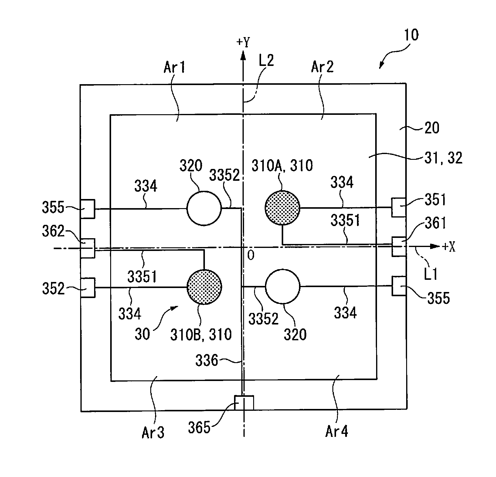
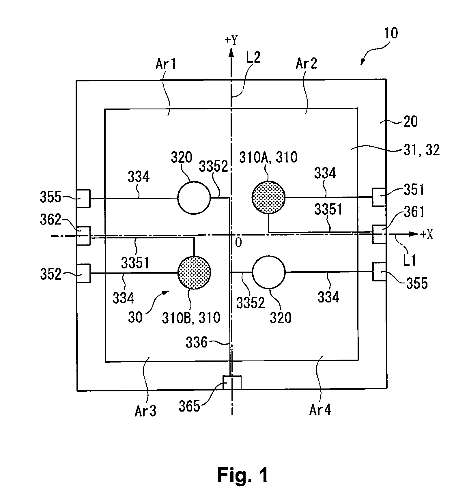
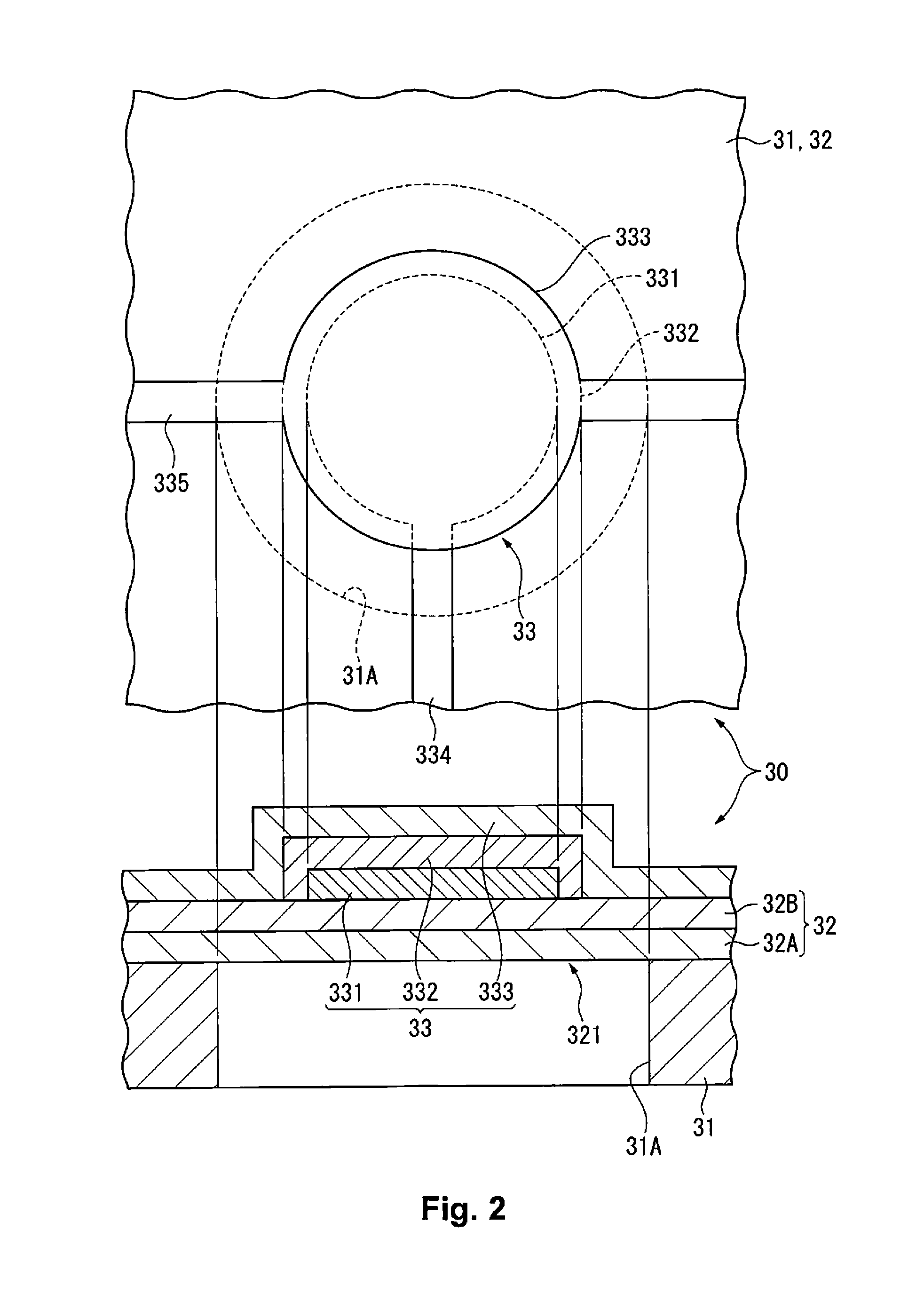
[0027]FIG. 1 is a plan view showing the general configuration of an ultrasonic sensor 10 of the present embodiment.
[0028]The ultrasonic sensor 10 is provided with a plurality of ultrasonic transducers 30 mounted on a sensor substrate 20. The ultrasonic sensor 10 is configured in a two-dimensional array structure in which the four ultrasonic transducers 30 are arranged at equal intervals along the X axis L1 and the Y-axis L2 in the form of a matrix on the sensor substrate 20, as shown in FIG. 1. The X axis L1 and Y-axis L2 are orthogonal axes in the plane of the sensor substrate 20, and are axes that follow the sides of the rectangular sensor substrate 20.
[0029]In the present embodiment, two of the four ultrasonic transducers 30 are used as transmission / reception dual-use elements 310A, 310B and the other two are used as transmitting elements 320...
second embodiment
[0079]FIG. 5 is an enlarged plan view showing the main part of the ultrasonic sensor 10B according to the second embodiment.
[0080]The ultrasonic sensor 10B is different from the ultrasonic sensor 10 having the two-dimensional array structure in that the transmission / reception dual-use elements 310 and the transmitting elements 320 are in a line-array structure arranged along a straight line, but the circuit configuration and the like are the same.
[0081]In other words, the transmission / reception dual-use elements 310A, 310B are arranged with predetermined pitch separation on the sensor substrate 20, and the transmitting elements 320 are arranged on the outer side of the transmission / reception dual-use elements 310A, 310B and with predetermined pitch separation from the transmission / reception dual-use elements 310A, 310B. Accordingly, the elements 310A, 310B, 320 are arranged in a single direction with equidistant interval separation.
[0082]The electrode lines 334, 3351, 3352, 336 are ...
third embodiment
[0089]FIG. 6 is an enlarged plan view showing the main part of the ultrasonic sensor 10C according to the third embodiment.
[0090]The ultrasonic sensor 10 of the first embodiment has two transmission / reception dual-use elements 310 and two transmitting elements 320 for a total of four elements 310, 320 arrayed in two dimensions. In contrast, the ultrasonic sensor 10C is different in that there are two transmission / reception dual-use elements 310 and 14 transmitting elements 320 for a total of 16 elements 310, 320 arrayed in two dimensions. In other words, the ultrasonic sensor 10C has four elements 310, 320 arrayed in the X-axis direction and four arrayed in the Y-axis direction.
[0091]The four elements arranged in proximity to the center point O of the two-dimensional array are the same as those in the first embodiment. In other words, two transmission / reception dual-use elements 310A, 310B are arranged in the second and third regions Ar2, Ar3 among the four regions divided by the X ...
PUM
 Abstract
Description
Claims
Application Information