Apparatus for improving reception sensitivity of public wave receiver by reducing noise externally-emitted in the public wave receiver

Active Publication Date: 2007-07-17
LG ELECTRONICS INC
View PDF19 Cites 16 Cited by
  • Summary
  • Abstract
  • Description
  • Claims
  • Application Information

AI Technical Summary

Benefits of technology

[0020]Accordingly, one object of the present invention is to solve the foregoing problems by preventing external emission of noise generated by power devices so as to improve reception sensitivity of a public wave receiver.
[0021]Another object of the present invention is to provide an antenna which is not influenced by noise generated by a public wave receiver in order to improve reception sensitivity of the receiver.
[0022]The foregoing and other objects and advantages are realized by providing an apparatus for improving reception sensitivity of a public wave receiver, including: a substrate formed in a power supply; at least one power device mounted on the substrate of the power supply, for supplying power by a switching operation; and a shielding plate being composed of a conductive material, including a shielding surface for shielding the top surfaces of the power devices, and mounting legs extended from the bottom surface of the shielding surface and mounted on the substrate, and preventing external transmission of noise generated by the power devices.
[0024]According to another aspect of the invention, an apparatus for improving reception sensitivity of a public wave receiver includes: a power device for performing a switching operation to stably supply power to the public wave receiver; shielding means for shielding noise generated by the power device; cooling means for lowering a high temperature due to the shielding means; and noise intercepting means for preventing noise from being transmitted to an antenna.
[0025]According to the present invention, noise generated by the power devices of the power supply is prevented from being transmitted through the connecting wire, especially the signal line, to receive reliable high quality signals.
[0026]In addition, the power devices generating switching noise can be stably used in the power supply of the public wave receiver, thereby relatively reducing a size and weight of the power supply for miniaturization.

Problems solved by technology

The emitted noise seriously generates failures in public wave reception of a public wave receiver.
It is thus impossible to receive normal public waves in a desired frequency band, which reduces reception sensitivity and generates noise.
However, the switching frequency and / or multiplied frequency generated by the power devices (3 of FIG. 1) is mingled with the frequency band which the antenna intends to receive, and produces noise.
Here, the switching frequency generated by the power devices 3 is transmitted to the connecting wire 7 of the antenna, and thus produces noise in the AM signals received by the pubic wave receiver.
As a result, normal frequency reception is impossible.

Method used


Image

  • Apparatus for improving reception sensitivity of public wave receiver by reducing noise externally-emitted in the public wave receiver
  • Apparatus for improving reception sensitivity of public wave receiver by reducing noise externally-emitted in the public wave receiver
  • Apparatus for improving reception sensitivity of public wave receiver by reducing noise externally-emitted in the public wave receiver

Examples


Embodiment Construction

[0037]The following detailed description will present an apparatus for improving reception sensitivity of a public wave receiver according to a preferred embodiment of the invention with reference to the accompanying drawings.

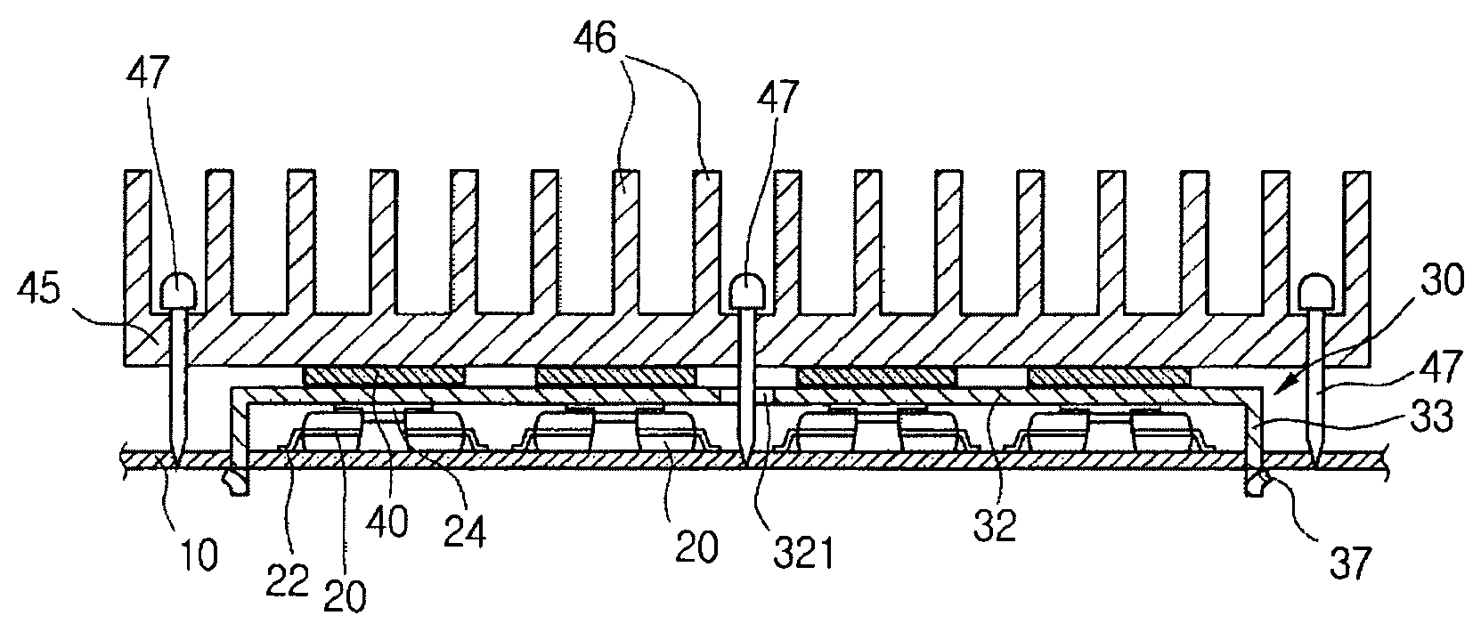
[0038]FIGS. 4 to 6 show the constitution of a power device installation part in the apparatus for improving reception sensitivity of the public wave receiver in accordance with the present invention.

[0039]As illustrated in FIGS. 4 to 6, the apparatus for improving reception sensitivity of the public wave receiver includes a substrate 10 of a power supply, heat emission conductors 24 for rapidly conducting heat generated in power devices 20, a shielding plate 30 for shielding the top surfaces of the power devices 20, adhering members 40 for surface-contacting the top surface of the shielding plate 30, and a heat sink 45 for surface-contacting the top surfaces of the adhering members 40, and for dissapating heat which is generated and conducted by the power devic...


PUM


Abstract

An apparatus for improving reception sensitivity of a public wave receiver includes power devices formed in a power supply of the public wave receiver, and a shielding plate for shielding noise generated by the power devices. A signal line for connecting an antenna used for the public wave receiver to a public wave receiver main body and a ground line are formed coaxially to each other by a shield layer.

Description

BACKGROUND OF THE INVENTION[0001]1. Field of the Invention[0002]The present invention relates to an apparatus for improving the reception sensitivity of a public wave receiver, and more particularly, to an apparatus for improving reception sensitivity of a public wave receiver by reducing noise externally-emitted in the public wave receiver, which generates serious noise due to switching operations of power devices built in a power supply of the receiver.[0003]2. Brief Description of the Background Art[0004]Recently, electronic digital products include special power supplies for stable and reliable supply of power. The power supply uses chip-type power devices for stably supplying power by switching operations in order to decrease the size and weight of the power supply.[0005]An SMPS (Switched Mode Power Supply) can also be employed as the power supply.[0006]FIG. 1 is a plan view illustrating the power supply where general power devices are mounted on a substrate, and FIG. 2 is a si...

Claims


Application Information

Patent Timeline
IPC IPC(8): H04B1/10H01Q1/02H01Q1/52H01Q7/00H04B1/38
CPCH01Q1/02H01Q1/526H01Q7/00H04B1/38H05K9/0028H05K1/0203
Inventor SEO, DONG HANKIM, JONG WOOKIM, CHAN TAEKWON, OH SUKLEE, JAE GEUN
Owner LG ELECTRONICS INC
Why Eureka
Try Eureka