

Glass antenna
- Summary
- Abstract
- Description
- Claims
- Application Information
AI Technical Summary
Benefits of technology
Problems solved by technology
Method used
Image

Examples
first embodiment
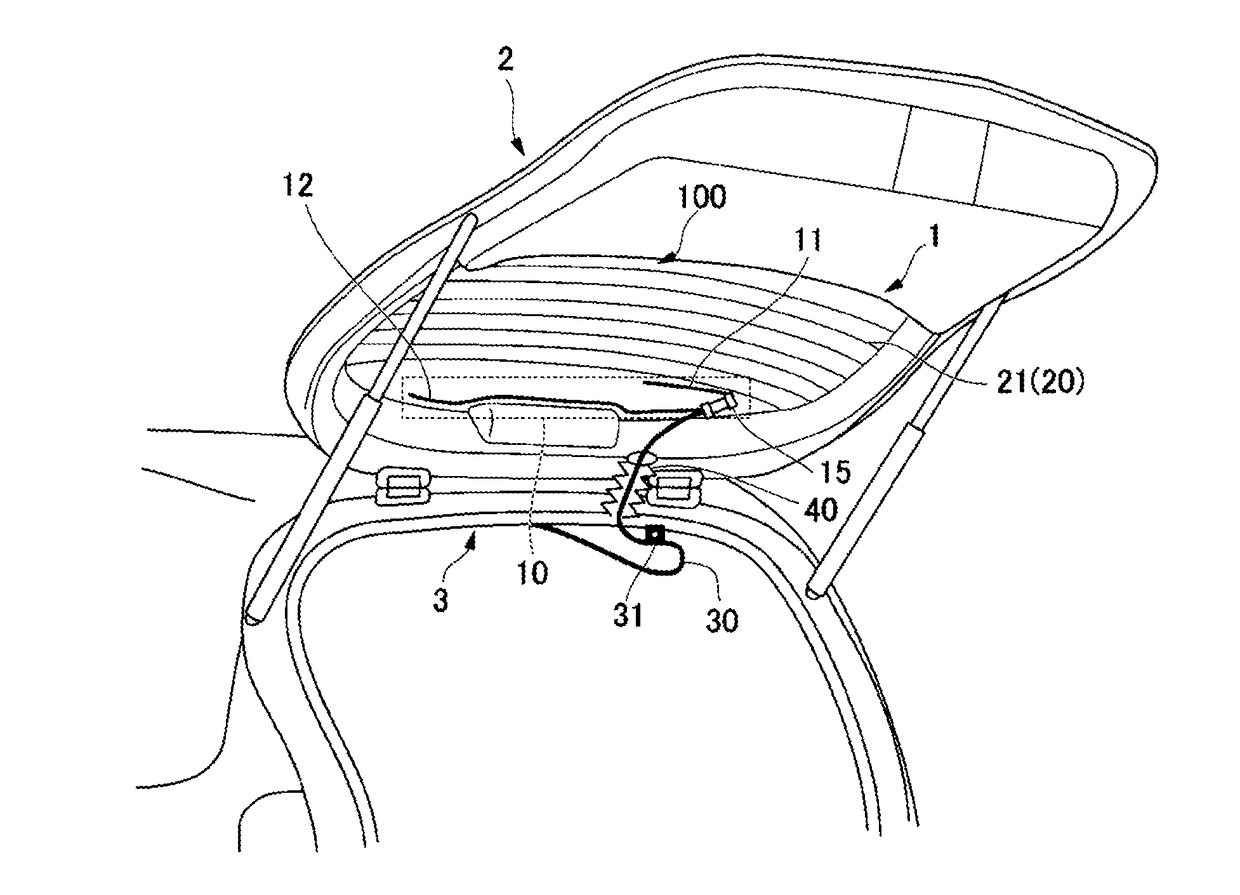
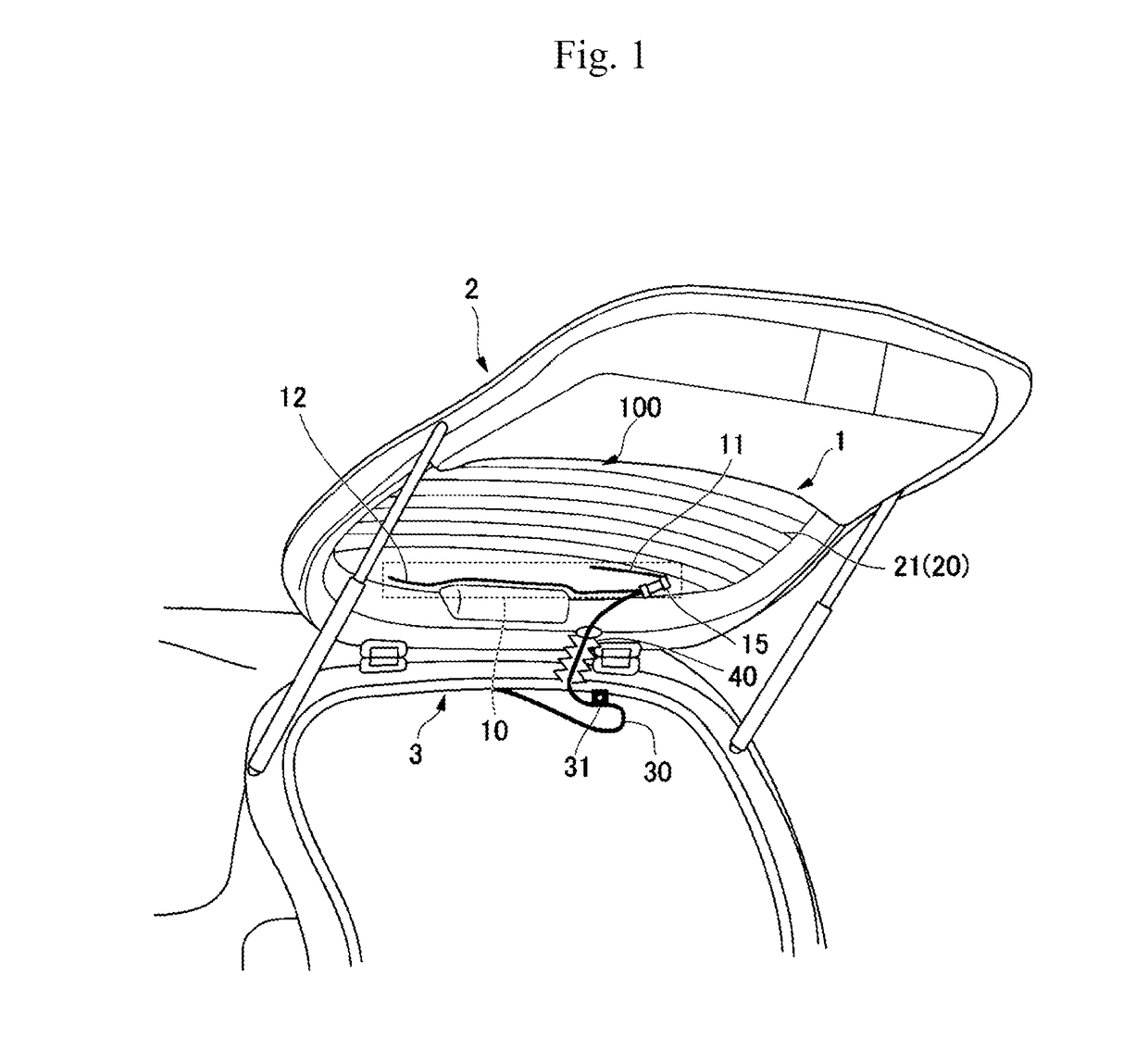
[0022]FIG. 1 is a view showing an example in which a glass antenna 1 according to a first embodiment is mounted on a vehicle.
[0023]As shown in FIG. 1, the glass antenna 1 is attached to a backdoor 2 of the vehicle (which is, for example, a hatchback type car). The backdoor 2 is, for example, made from resin, and openably and closably attached to a rear portion of the vehicle.
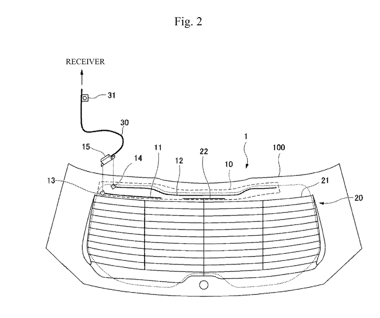
[0024]The glass antenna 1 has a rear glass 100 for the vehicle. A DAB antenna portion 10 and a defogger 20 including heating wires 21 are disposed in the rear glass 100. In addition, the DAB antenna portion 10 has a first element 11, a second element 12, and a DAB amplifier 15. The DAB antenna portion 10 is connected to a coaxial cable 30 through the DAB amplifier 15.
[0025]The DAB antenna portion 10 is a bipolar type antenna for receiving radio waves in a DAB frequency band. “DAB” is a standard for Digital Audio Broadcast, which is a digital radio. In addition, DAB includes two different frequency bands, that is...
second embodiment
[0065]Next, a glass antenna 1a according to a second embodiment will be described with reference to FIG. 4.
[0066]FIG. 4 is a view showing a configuration example of the glass antenna 1a according to the second embodiment. In FIG. 4, constituents the same as those in FIG. 2 are referenced correspondingly, and their description will be omitted.
[0067]In addition, a configuration in which the glass antenna 1a is mounted on a vehicle is fundamentally the same as that in the first embodiment shown in FIG. 1. Therefore, description of the configuration will be omitted. In the embodiment, the backdoor 2 is made from resin in the same manner as in the first embodiment.
[0068]The glass antenna 1a according to the embodiment is different from the first embodiment in that the second element 12a is expanded to a right region (a blank region on the right side) of the defogger 20, and in that an L-shaped element 22a is provided in place of the T-shaped element 22.
[0069]As shown in FIG. 4, the glass...
third embodiment
[0080]Next, a glass antenna 1b according to a third embodiment will be described with reference to FIG. 5.
[0081]FIG. 5 is a view showing a configuration example of the glass antenna 1b according to the third embodiment. In FIG. 5, constituents the same as those in FIG. 2 are referenced correspondingly, and their description will be omitted.
[0082]In addition, a configuration in which the glass antenna 1b is mounted on a vehicle is fundamentally the same as that in the first embodiment shown in FIG. 1. Therefore, description of the configuration will be omitted. In the embodiment, the backdoor 2 is made from resin in the same manner as in the first embodiment.
[0083]The glass antenna 1b according to the embodiment is different from the first embodiment in that the hot-side feeding point 13 and the earth-side feeding point 14 are disposed in a central portion of an upper region of a rear glass 100b, and in that the second element 12b is extended to a lower region of the defogger 20. In ...
PUM
 Abstract
Description
Claims
Application Information