Two-Stage Multichannel LED Driver with CLL Resonant Circuit

a multi-channel led driver and resonant circuit technology, applied in the direction of lighting equipment, electrical equipment, light sources, etc., can solve the problems of inability to achieve high efficiency, impractical number of components, and dramatic change of current and consumed power as well as luminous output, etc., and achieve high efficiency

Active Publication Date: 2015-10-08
VIRGINIA TECH INTPROP INC
View PDF10 Cites 11 Cited by
  • Summary
  • Abstract
  • Description
  • Claims
  • Application Information

AI Technical Summary

Benefits of technology

[0009]It is therefore an object of the present invention to provide a simple driver circuit having a limited number of circuit components for multiple strings of LEDs which may constitute significantly unbalanced loads while providing substantially balanced currents and equal luminous brightness from all LEDS in all strings and which can provide and maintain high efficiency over a wide range of controllable brightness.
[0010]It is another object of the invention to provide an LED driver circuit in which complexity of driver circuitry and operation are substantially unaffected by the number of LED strings driven in a current-balanced manner, regardless of imbalance of loads presented by the LED strings.

Problems solved by technology

Therefore, a small variation of the forward voltage will result in a dramatic change of the current and consumed power as well as luminous output.
Therefore, the current balance among LED strings is highly critical.
However, these methods require an impractical number of components and adequately high efficiency cannot be achieved especially when a linear current regulator is used.
However, the accuracy of current balancing is very sensitive to the impedance of the passive components.
In addition, the power dissipation in the series resistor is substantial when used for current balancing; reducing efficiency, often to an unacceptable degree, particularly if dimming is required.
For example, the LED driver is required to generate AC current or AC voltage for such reactive components to function properly; increasing component count, cost and complexity and compromising power density and efficiency.
However, the operation of this LED driver is somewhat complicated especially when larger numbers of LED strings are driven at the same time.
Therefore, higher efficiency can not be guaranteed under conditions of wide variation of input voltage.
However, for this one-stage MC3 LLC resonant LED driver, it is very difficult to achieve low dimming since its efficiency decreases dramatically when it is working under low dimming conditions due to its switching frequency being pushed much higher than the resonant frequency.

Method used


Image

  • Two-Stage Multichannel LED Driver with CLL Resonant Circuit
  • Two-Stage Multichannel LED Driver with CLL Resonant Circuit
  • Two-Stage Multichannel LED Driver with CLL Resonant Circuit

Examples


Embodiment Construction

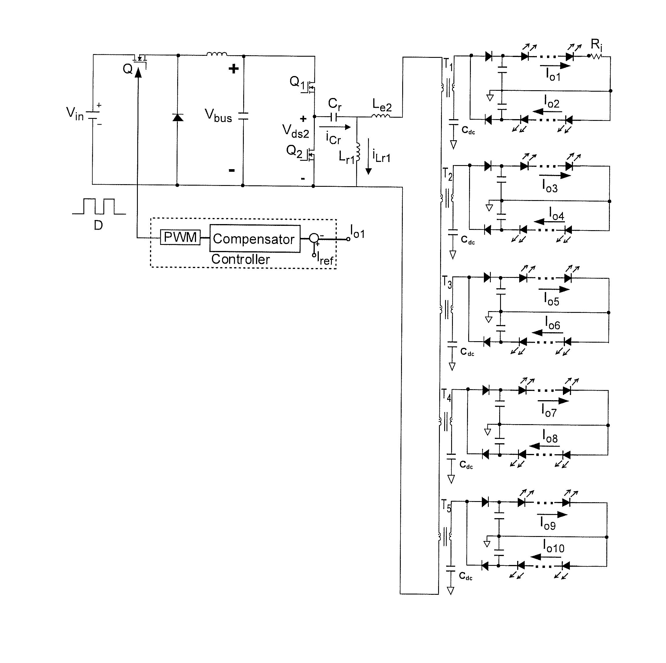
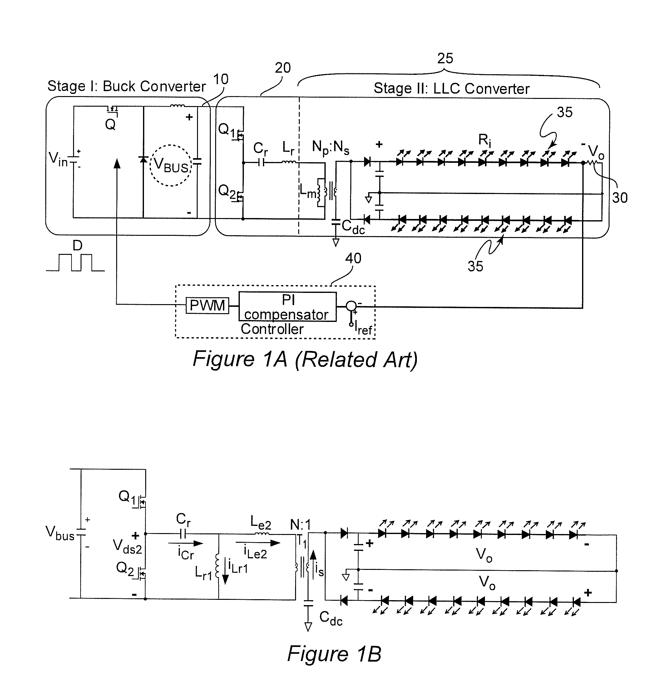
[0024]Referring now to the drawings, and more particularly to FIG. 1A, there is shown a schematic diagram of a generalized two-stage LLC resonant LED driver circuit over which the present invention provides significant improvements and advantages. Since this diagram is generalized and arranged to facilitate comparison of the invention therewith to better convey an understanding of the invention, no portion of FIG. 1A is admitted to be prior art in regard to the present invention and FIG. 1A has, accordingly, been labeled as “Related Art”. A similar circuit is schematically depicted in FIGS. 1 and 3 of U.S. patent application Ser. No. 14 / 140,008, filed Dec. 24, 2013, which is hereby incorporated by reference in its entirety.

[0025]The LED driver depicted in FIG. 1A provides a lower dimming ratio than other known LED drivers and does so with a relatively small number of components. The small number of components conveniently provides for comparatively high power density and reduced cos...


PUM


Abstract

Zero voltage switching (ZVS) is provided in switches of a switching circuit in a second stage of a power converter by an inductor of a CLL resonant circuit connected in parallel with both a primary winding of one or more transformers connected in series and an output of the switching circuit so that the parasitic output capacitances of the switches can be charged and discharged, respectively, during the dead-time of the switching circuit by current in the inductor and independently of current in the magnetizing inductance of the transformer. Therefore, the magnetizing inductance of the transformer can be made sufficiently large to balance currents delivered to respective loads that may be unbalanced as is particularly desirable for driving a plurality of LED strings for illumination and is consistent with controlled dimming of the LED strings. A current sensor such as a resistance can be place in any LED string and all transformer modules and string currents cross regulated,

Description

CROSS-REFERENCE TO RELATED APPLICATIONS[0001]This application claims benefit of priority of U. S. Provisional Application 61 / 975,445, filed Apr. 4, 2014, which is hereby incorporated by reference in its entirety.FIELD OF THE INVENTION[0002]The present invention generally relates to power converters suitable for driving electronic devices and elements and, more particularly, to power converters for driving light-emitting diodes (LEDs) and organic LEDs arranged in a plurality of parallel strings, particularly for illumination applications and which avoid criticality of balance between such strings.BACKGROUND OF THE INVENTION[0003]Light-emitting (LEDs) diodes have been known for a number of years and have been used in electronic displays of increasing functionality and resolution. Organic light-emitting diodes (OLEDs) have recently been developed and have several properties such as improved color resolution and have become commercially used in high-quality large-screen televisions. Fur...

Claims


Application Information

Patent Timeline
Patent Type & Authority Applications(United States)
IPC IPC(8): H05B33/08H05B44/00
CPCH05B33/0815H05B33/0851H05B33/0827H05B45/10H05B45/382H05B45/375H05B45/39
Inventor CHEN, XUEBINGHUANG, DAOCHENGLI, QIANGLEE, FRED C.
Owner VIRGINIA TECH INTPROP INC
Why Eureka
Try Eureka