Mobile crane, support device, and assembly process for a support device

a technology of supporting device and mobile crane, which is applied in the direction of cranes, vehicle maintenance, transportation and packaging, etc., can solve the problems of increasing the cost of requesting a driving permit, making the threading of sliding beams into sliding beam boxes at the installation point more difficult, and achieving a larger area of operation

Active Publication Date: 2015-10-15
LIEBHERR WERK EHINGEN
View PDF2 Cites 3 Cited by
  • Summary
  • Abstract
  • Description
  • Claims
  • Application Information

AI Technical Summary

Benefits of technology

[0023]Furthermore, the present invention relates to a process for the installation of at least one support device on a mobile crane, particularly on the crane in accordance with the invention or an advantageous configuration of the crane in accordance with the invention, as the case may be. In accordance with the invention, it is proposed for one or several auxiliary installation supports to be mounted onto the one or several fixed partial sliding beam boxes of the mobile crane. The mobile crane can be used, for example, in road traffic with one or several mounted auxiliary installation supports, without exceeding the permissible total weight for road traffic. In particular, the installation of two auxiliary installation supports on the chassis of the mobile crane is conceivable.
[0024]By means of the mounted auxiliary installation supports, such as in the form of one or several support cylinders, for example, a support base that is temporarily enlarged relative to the chassis is achieved, so that the crane, by means of its boom, lifts one or several support devices of a separate transport device and can pass into the area of the one or several fixed partial sliding beam boxes on the vehicle framework of the mobile crane. Because of the mounted auxiliary installation supports, it is possible for the installation to work in a larger area of operation.

Problems solved by technology

If the total weight exceeds the limit of 100 T, however, then the expense for requesting a driving permit becomes considerably higher or no permits may be issued, as the case may be.
The small bearing clearance and the specific weight of the support beam, however, make the threading of the sliding beam into the sliding beam box at the installation point more difficult.

Method used


Image

  • Mobile crane, support device, and assembly process for a support device
  • Mobile crane, support device, and assembly process for a support device
  • Mobile crane, support device, and assembly process for a support device

Examples


Embodiment Construction

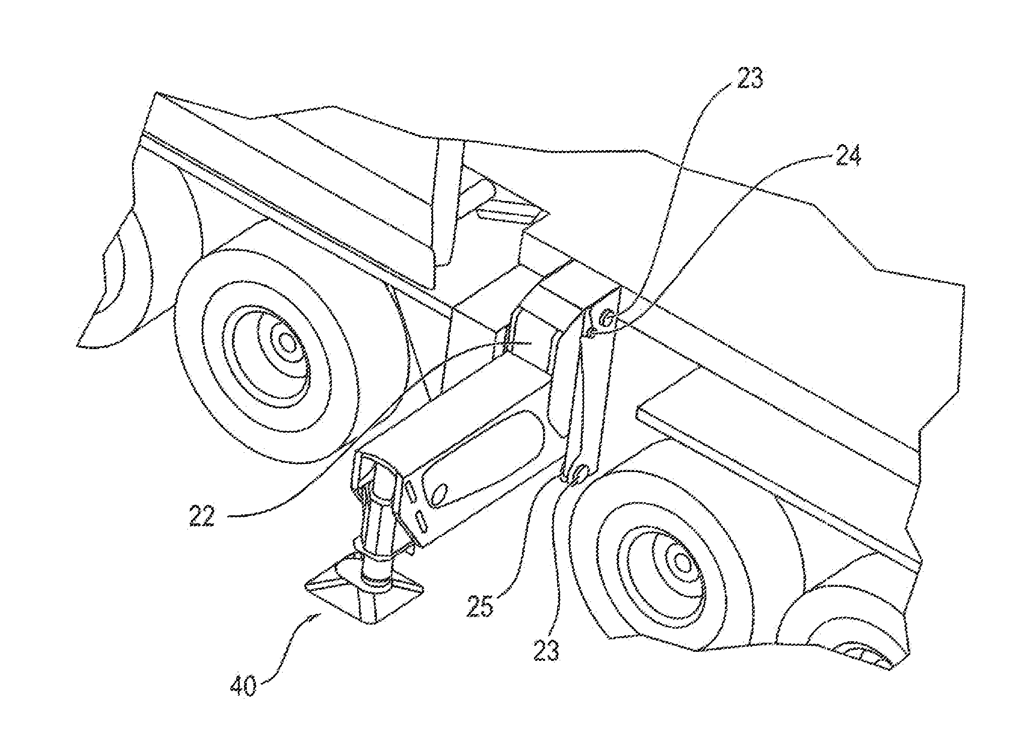
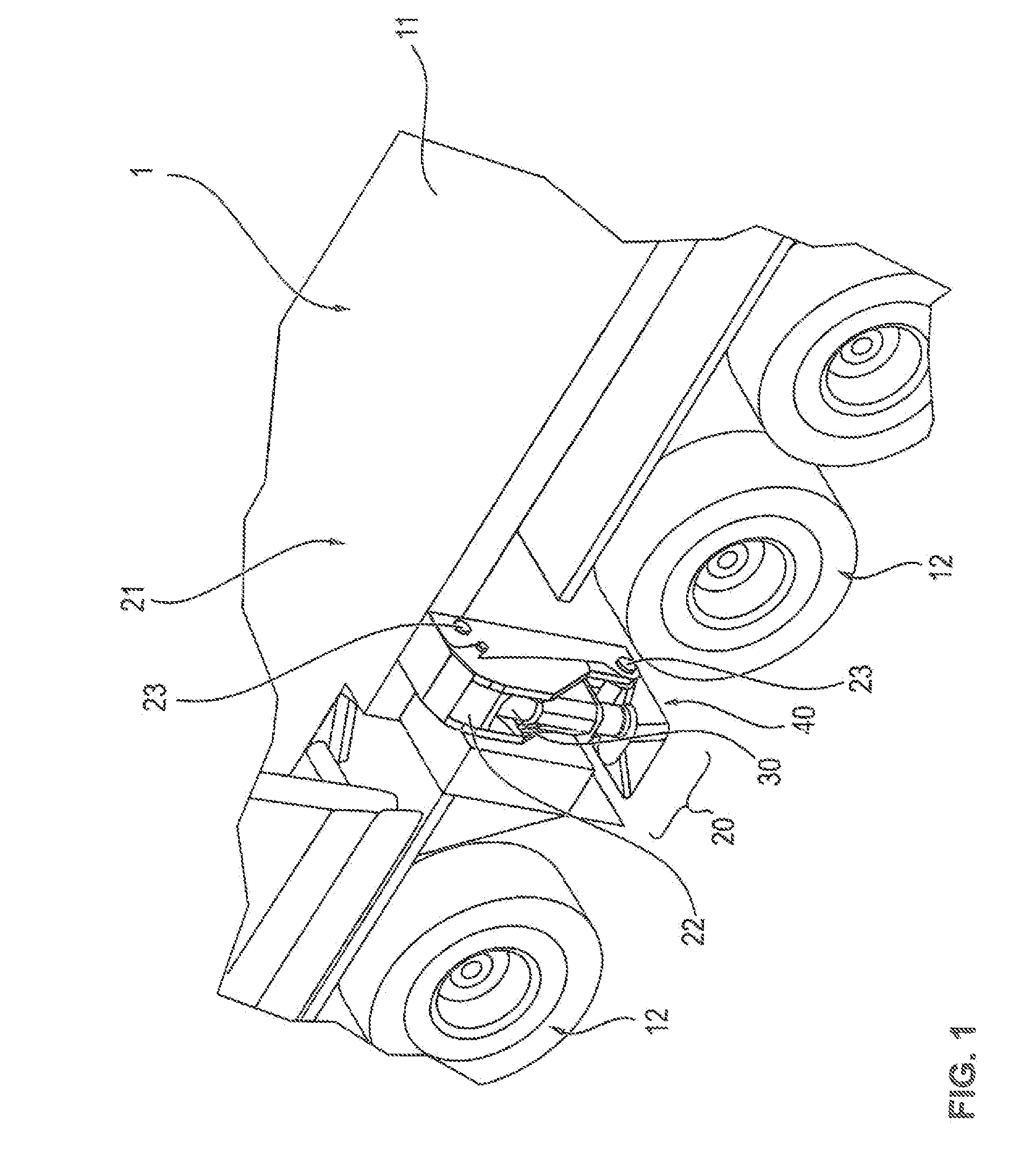
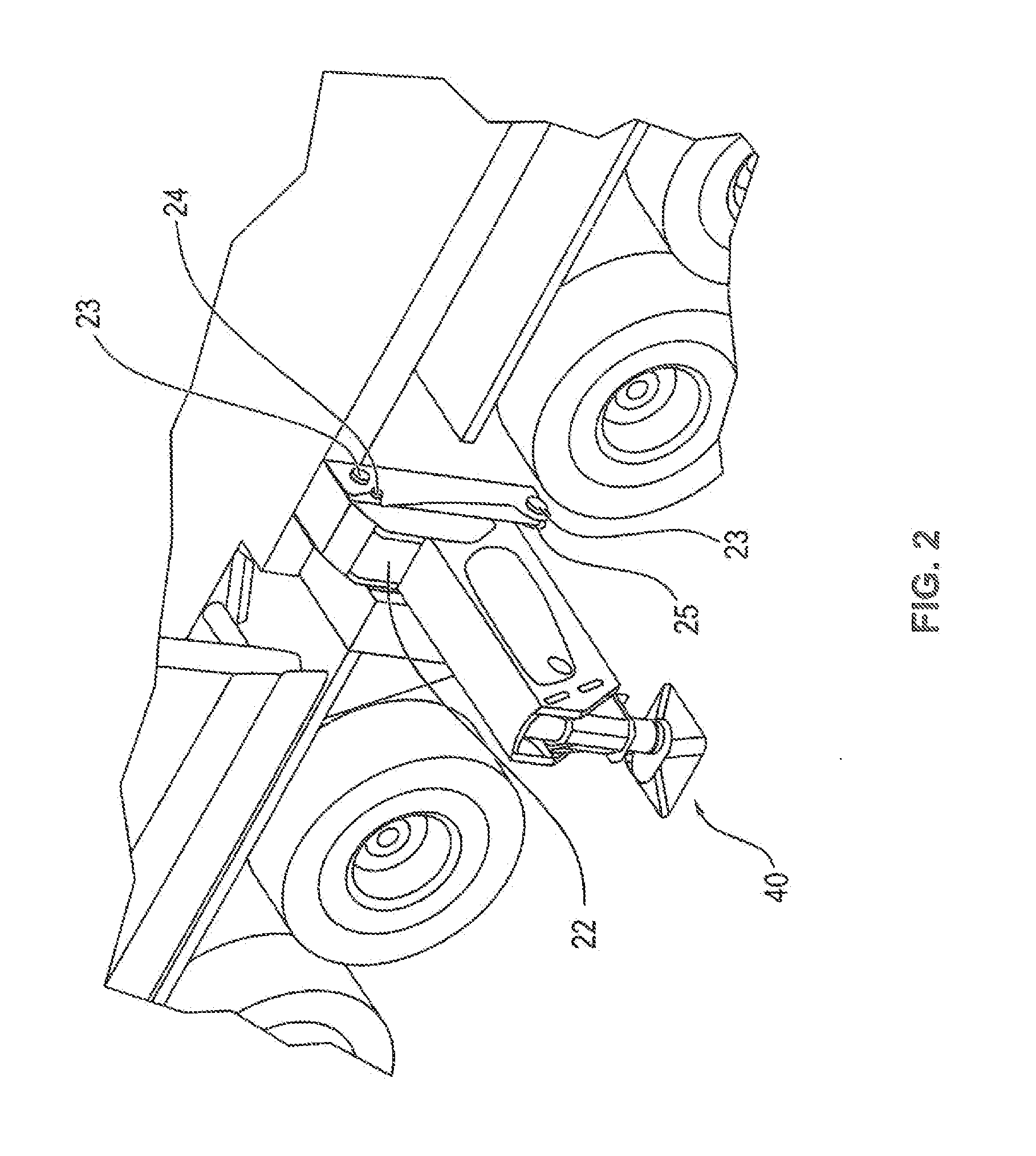
[0035]FIG. 1 depicts a detailed section of the crane in accordance with the invention 1. A partial extract of the undercarriage of the crane with the multi-axle chassis 11 is to be noted. The number of vehicle axles 12 is not significant. For the operation of the crane, it is necessary to support the mobile crane by means of several support devices, in order to thereby minimize the danger of tipping upon larger load radii. Beams sliding in a telescopable manner, which can be laterally telescoped out in the transverse direction of the vehicle, are used as support devices. The specifically distributed positioning of the individual support devices on the vehicle is less relevant for the core concept in accordance with the invention. For example, two or more support devices can be installed on each side of the vehicle.

[0036]For the road transport of the mobile crane 1, the permissible total weight in accordance with road traffic regulations must be observed. For that purpose, certain cr...


PUM

PropertyMeasurementUnit
weightaaaaaaaaaa
total weightaaaaaaaaaa
load-bearing capacityaaaaaaaaaa

Abstract

This invention relates to a mobile crane with a vehicle framework and at least one support device positioned on the vehicle framework, whereby the at least one support device comprises a sliding beam box and at least one sliding beam supported therein in a telescopable manner, whereby the sliding beam box consists of a fixed partial sliding beam box and of a detachable partial sliding beam box, and whereby the fixed partial sliding beam box is firmly fixed to the mobile crane, particularly on the vehicle framework, and the detachable partial sliding beam box is detachably connected or connectable with the fixed partial sliding beam box.

Description

BACKGROUND OF THE INVENTION[0001]The invention relates to a mobile crane with a vehicle framework and at least one support device positioned on the vehicle framework, whereby the at least one support device comprises a sliding beam box and at least one sliding beam supported therein in a telescopable manner.[0002]Mobile cranes, because of their very nature, usually have several vehicle axles by means of which the mobile crane can be moved down a road. Because of the current legislation, a maximum axle load of 12 T is thereby permitted for road travel. As a rule, driving permits for large devices with a total weight of up to 100 T are issued relatively easily and quickly. If the total weight exceeds the limit of 100 T, however, then the expense for requesting a driving permit becomes considerably higher or no permits may be issued, as the case may be.[0003]In order to observe the legally specified maximum weight for road travel, it is thus known to transport individual components of ...

Claims


Application Information

Patent Timeline
Patent Type & Authority Applications(United States)
IPC IPC(8): B66C23/78B66C23/80
CPCB66C23/80B66C23/78
Inventor BOOS, BERND
Owner LIEBHERR WERK EHINGEN
Why Eureka
Try Eureka