Sensing structure of touch panel

a touch panel and sensing technology, applied in capacitance measurement, resistance/reactance/impedence, instruments, etc., can solve the problems of limiting the requirement of volume and screen size is extremely strict, and the drawback of higher manufacturing cost and complicated processes, so as to enhance enhance the touch operation region. , the effect of enhancing the sensitivity of the touch panel

Active Publication Date: 2015-11-24
HEFEI SITRONIX CO LTD
View PDF7 Cites 3 Cited by
  • Summary
  • Abstract
  • Description
  • Claims
  • Application Information

AI Technical Summary

Benefits of technology

[0009]An objective of the present invention is to provide a sensing structure of touch panel, which uses the shape of its electrodes and the layout of wires for disposing two or more electrodes in each electrode group and thus enhancing the sensitivity of touch sensing.
[0010]Another objective of the present invention is to provide a sensing structure of touch panel, which increases the touch operation region in each electrode group for enhancing the accuracy of touch sensing.
[0011]Still another objective of the present invention is to provide a sensing structure of touch panel, which increases the touch operation region in each electrode group for enhancing the accuracy of multi-touch sensing.
[0012]Another objective of the present invention is to provide a sensing structure of touch panel, which shrinks the width of wires for reducing the area of the wires in the electrode groups. By using this method, the problem of reduced area for electrodes caused by excess wires while disposing multiple electrodes in the electrode groups can be thereby solved.
[0013]For achieving the objectives described above and their effects, the present invention discloses a sensing structure of touch panel, which comprises a plurality of electrode groups disposed on a substrate. The substrate has a first side and a second side corresponding to each other. Each electrode group comprises a first external electrode, a second external electrode, and a plurality of internal electrodes. The first external electrode is disposed on the first side and has a first external main electrode and a first external sub electrode. The first external sub electrode is connected to one side of the first external main electrode. Besides, the first external sub electrode is zigzag and faces the second side. The second external electrode is disposed on the second side and has a second external main electrode and a second external sub electrode. The second external sub electrode is connected to one side of the second external main electrode. Besides, the second external sub electrode is zigzag and faces the first side. The plurality of internal electrodes are disposed between the first external electrode and the second external electrode, and have an internal main electrode, a first internal sub electrode, and a second internal sub electrode, respectively. The first internal sub electrode is connected to one side of the internal main electrode. Besides, the first internal sub electrode is zigzag and faces the first side. The second internal sub electrode is connected to the other side of the internal main electrode. Besides, the second internal sub electrode is zigzag and faces the second side. The plurality of internal electrodes are arranged in series. In addition, the first internal sub electrode of a first internal electrode of the plurality of internal electrodes and the first external sub electrode are complementary and electrically isolated. Thereby, according to the present invention, the disposable number of electrodes in each electrode group can be increased by disposing the first external electrode, the second external electrode, and the internal electrodes, all having zigzag sub electrodes, in each electrode group. Hence, the sensitivity of touch sensing for the sensing structure of touch panel can be enhanced as well. Moreover, by increasing the touch operation region in each electrode group, the sensitivity and accuracy of touch sensing are increased. Furthermore, by increasing the touch operation region in each electrode group, more accurate multi-touch capability is thus provided.
[0014]Besides, the electrode groups further comprise a plurality of wires coupled to the first external electrode, the second external electrode, and the plurality of internal electrodes, respectively, and extending from the first side to the second side; the plurality of wires are disposed on both sides of the electrode groups alternately. After passing the length of an internal electrode, the widths of the plurality of wires are reduced. Thereby, by disposing the wires on both sides of the electrode groups alternately and by reducing the widths of the plurality of wires after passing the length of an internal electrode, the area occupied by the wires in each electrode group is reduced. Hence, the disposable number of electrodes in each electrode group can be increased.

Problems solved by technology

In particular, for portable electronic products, the requirements in volume and screen size are extremely strict.
Nonetheless, a double-layer capacitive touch sensor requires disposing electrodes on the top and bottom surfaces of the glass substrate, respectively, and hence leading to the drawbacks of higher manufacturing costs and complicated processes.
Thereby, it has only two touch locations, which limit its sensitivity.
In addition, the layout of its wires shrinks the area for the electrodes, making it is not possible to increase the sensitivity of touch sensing by disposing more electrodes in each electrode group.

Method used


Image

  • Sensing structure of touch panel
  • Sensing structure of touch panel
  • Sensing structure of touch panel

Examples


Embodiment Construction

[0024]In order to make the structure and characteristics as well as the effectiveness of the present invention to be further understood and recognized, the detailed description of the present invention is provided as follows along with embodiments and accompanying figures.

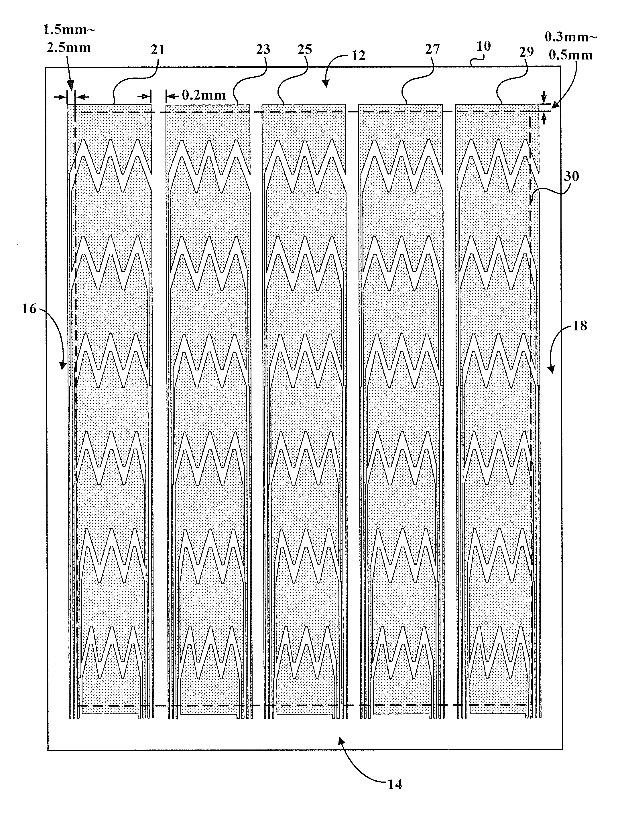
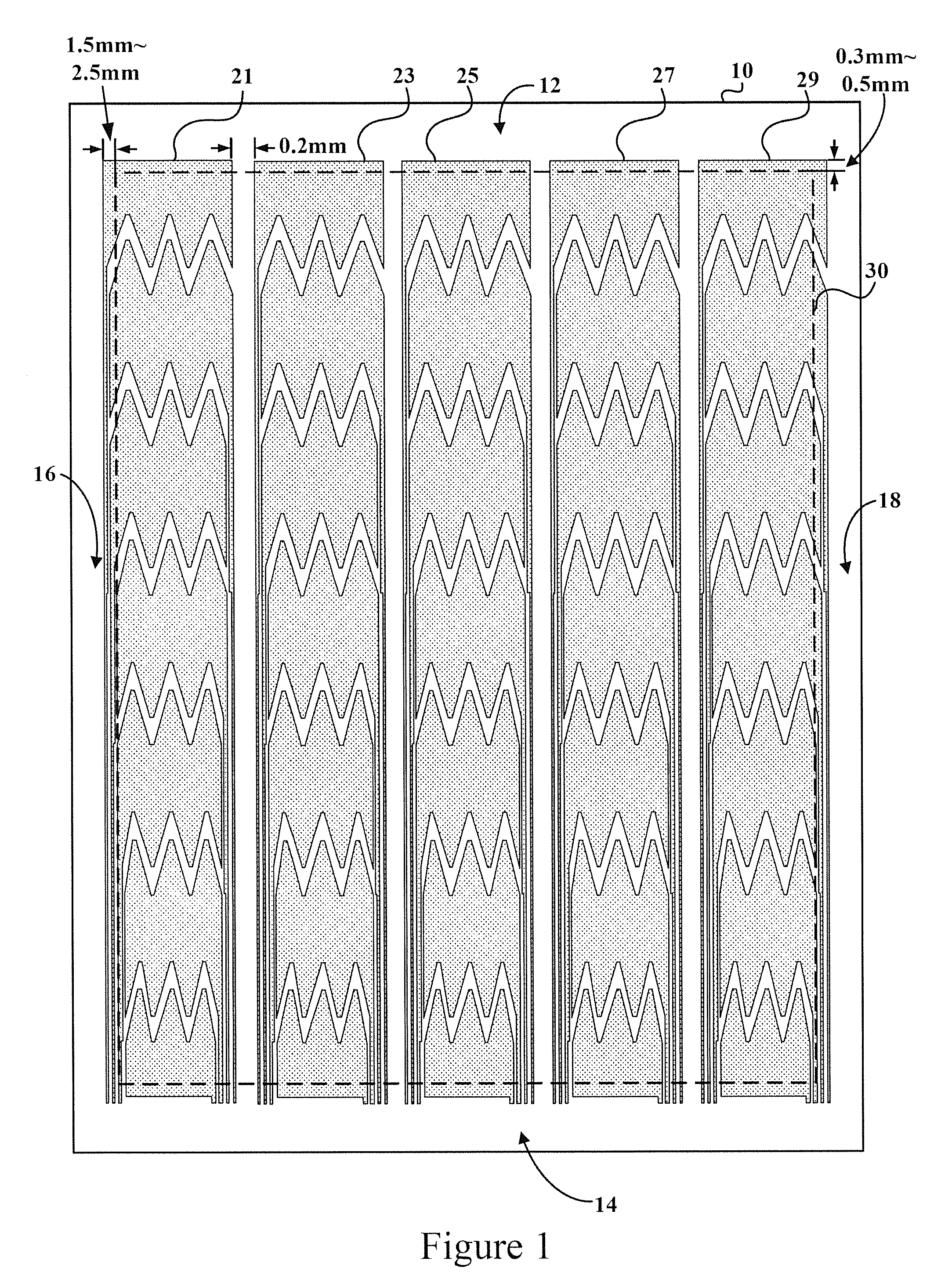
[0025]FIG. 1 shows a schematic diagram of the sensing structure of touch panel according to a preferred embodiment of the present invention. As shown in FIG. 1, the sensing structure of touch panel according to the present invention comprises a substrate 10 and a plurality of electrode groups 21, 23, 25, 27, 29. The substrate 10 has a first side 12 and a second side 14 corresponding to each other and has a third side 16 and a fourth side 18 corresponding to each other. The plurality of electrode groups 21, 23, 25, 27, 29 are arranged in parallel on the substrate 10 with a distance therebetween. According to the present embodiment, the distance between the plurality of electrode groups 21, 23, 25, 27, 29 is selected...


PUM

PropertyMeasurementUnit
widthaaaaaaaaaa
widthaaaaaaaaaa
overlap lengthaaaaaaaaaa

Abstract

The present invention relates to a sensing structure of touch panel, which comprises a plurality of electrode groups disposed on a substrate. The substrate has a first side and a second side. Each electrode group comprises a first external electrode, a second external electrode, a plurality of internal electrodes, and a plurality of wires. The first external electrode is disposed on a first side; the second external electrode is disposed on the second side; the plurality of internal electrodes are disposed between the first external electrode and the second external electrode; and the plurality of wires are disposed on both sides of the electrode group alternately. Thereby, by disposing the first external electrode, the second external electrode, and the internal electrodes, all being zigzag, the disposable number of electrodes in each electrode group is increased. Accordingly, the sensitivity of touch sensing for the sensing structure of touch panel is enhanced.

Description

REFERENCE TO RELATED APPLICATION[0001]This Application is based on Provisional Patent Application Ser. No. 61 / 608,176, filed 8 Mar. 2012, currently pending.FIELD OF THE INVENTION[0002]The present invention relates generally to a structure of touch panel, and particularly to a sensing structure of touch panel.BACKGROUND OF THE INVENTION[0003]In recent years, various electronic products are being developed in the trend of easy operation, small size, and large screen. In particular, for portable electronic products, the requirements in volume and screen size are extremely strict. Thereby, many electronic products integrate the touch panel with the LCD panel in order to save the area required by keyboards or keypads and thus enlarging the disposable area on the screen.[0004]Depending on their sensing principle, general touch panels can be categorized into resistive, capacitive, infrared, and ultrasonic types. Thanks to their advantages of dust repellence, scratch resistance, and high re...

Claims


Application Information

Patent Timeline
Patent Type & Authority Patents(United States)
IPC IPC(8): G01R27/26G02F1/1333G06F3/044
CPCG01R27/2605G06F3/044G02F1/13338G06F3/0443G06F3/0448
Inventor HERMAN
Owner HEFEI SITRONIX CO LTD
Why Eureka
Try Eureka