Energy management control system suitable for solar-powered unmanned aerial vehicle and control method thereof

a technology of solar energy and control system, which is applied in the direction of energy-efficient board measures, battery/fuel cell control arrangements, light to electrical conversion, etc., can solve the problems of difficult to solve contradictions, the maximum output power of the power system often cannot meet the requirements of take-off, climbing or maneuvering flight, etc., to achieve maximum power output, improve the power system efficiency of solar-powered, and improve the flight performance of the aircraft

Active Publication Date: 2022-05-03
ZHEJIANG UNIV
View PDF13 Cites 2 Cited by
  • Summary
  • Abstract
  • Description
  • Claims
  • Application Information

AI Technical Summary

Benefits of technology

[0004]The purpose of the present disclosure is to provide an energy management control system suitable for a solar-powered unmanned aerial vehicle and a control method thereof aiming at the shortcomings of the prior art. The power management scheme of single battery pack and double outputs is used, which can realize the power output in a certain voltage range. The input voltage of the Electronic Speed Controller (ESC) and the accelerator input amount of the ESC are jointly adjusted and controlled through corresponding control strategies, so as to improve the overall efficiency of the power system, thereby improving the endurance time of an unmanned aerial vehicle.
[0019]Compared with the prior art, the present disclosure has the following beneficial effects.
[0020]Different from the traditional scheme of changing accelerator amount with constant voltage, it is necessary to use higher battery pack voltage to ensure maximum power output. In the scheme design of the present disclosure, because a specific battery pack power supply scheme is used, it can match the design point (the cruising operating point) of the solar-powered unmanned aerial vehicle, improve the power system efficiency of the solar-powered unmanned aerial vehicle during cruising stage, and further improve the flight performance of the aircraft. When the system judges that it needs high power demand, the onboard controller controls the second DC-DC circuit to output a voltage higher than the battery pack to supply power to the ESC. Combined with the control of the accelerator amount of the ESC, the power system can still maintain high system efficiency at high power output.
[0021]It is worth noting that, compared with the scheme of directly adding an adjustable DC-DC circuit behind the battery pack and simultaneously controlling its output voltage and the accelerator amount of the ESC, although the scheme of the present disclosure can also improve the efficiency of the power system in a large operating area (including the state from low-power cruising to high-power maneuvering, etc.), in the design process of the scheme of the present disclosure, taking into account that the solar-powered unmanned aerial vehicle has a special operating point of cruising state, the scheme design of directly supplying power to the power unit by the battery pack is used. According to the scheme of the present disclosure, the system efficiency can be further improved on the basis of the above scheme. Specifically, the conversion efficiency of the adjustable variable voltage DC-DC circuit is 92%-96% during operation. In the above scheme, regardless of whether the solar-powered unmanned aerial vehicle is in low-power cruise or high-power maneuver state, the system power can pass through the adjustable DC-DC circuit to the ESC, and there will be 4%-8% of power loss. In such a manner that the battery pack directly supplies power to the power unit, in the low-power cruise stage, the system power will not pass through the adjustable DC-DC circuit to the ESC, so as to avoid the electric energy loss on the adjustable DC-DC circuit. The cruising state of the solar-powered unmanned aerial vehicle occupies most of the total flight mission time. therefore, the design of the present disclosure can significantly improve the efficiency of the power system of the solar-powered unmanned aerial vehicle, thereby improving the flight performance of the aircraft.

Problems solved by technology

However, at the design point (the cruise operating point), because the operating power at this time is less than ¼ of the rated power, it deviates from the high-efficiency range of the power system.
However, if the power system is matched according to the cruise operating point as the design point, the maximum output power of the power system often cannot meet the requirements of take-off, climbing or maneuvering flight.
This is a contradiction that is difficult to solve under the traditional control scheme.
In the above scheme, regardless of whether the solar-powered unmanned aerial vehicle is in low-power cruise or high-power maneuver state, the system power can pass through the adjustable DC-DC circuit to the ESC, and there will be 4%-8% of power loss.

Method used


Image

  • Energy management control system suitable for solar-powered unmanned aerial vehicle and control method thereof
  • Energy management control system suitable for solar-powered unmanned aerial vehicle and control method thereof
  • Energy management control system suitable for solar-powered unmanned aerial vehicle and control method thereof

Examples


Embodiment Construction

[0029]The present disclosure will be further explained with reference to the drawings and specific embodiments.

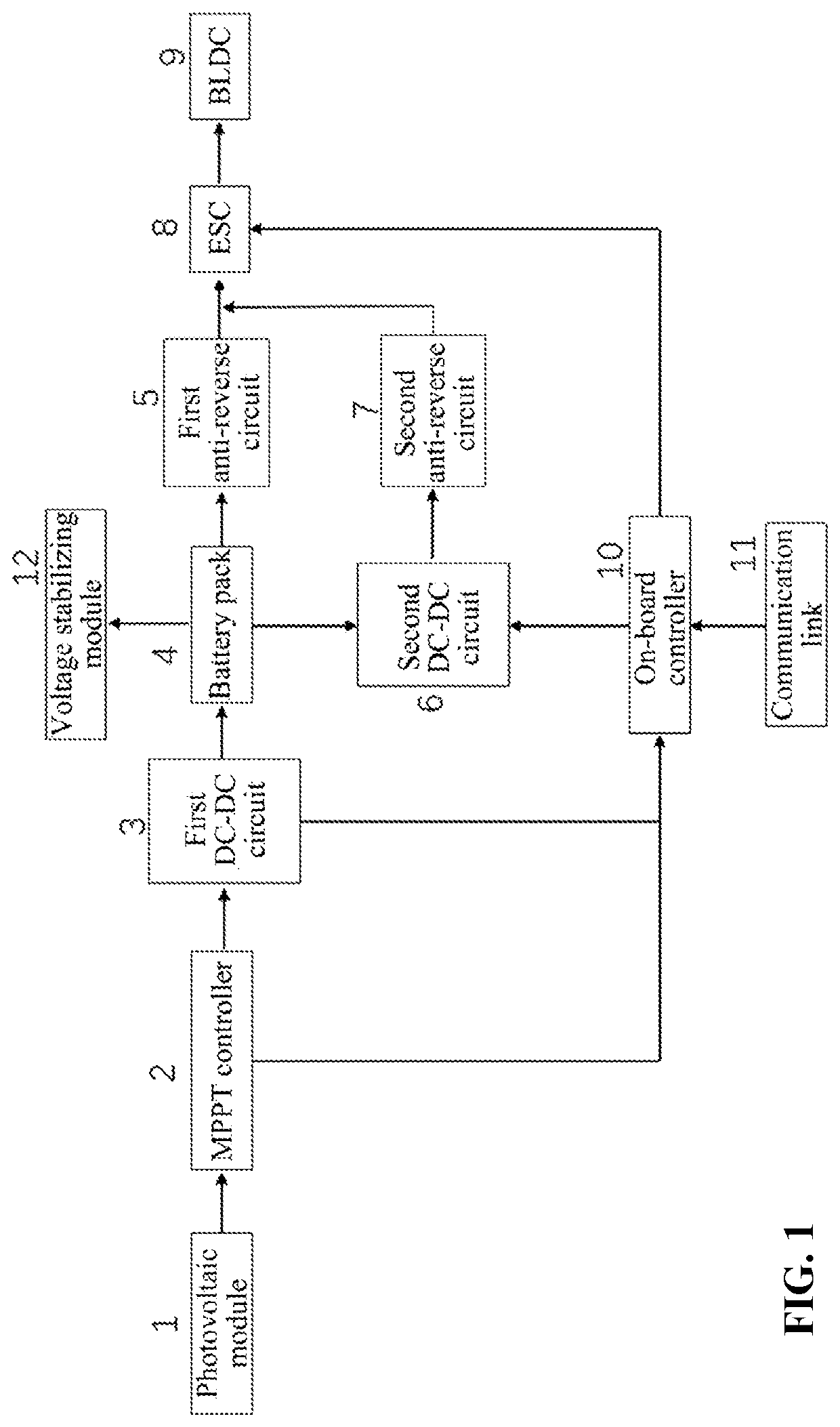
[0030]As shown in FIG. 1, this example mainly provides an energy management system suitable for a solar-powered unmanned aerial vehicle, comprising a photovoltaic module, an MPPT controller, a first DC-DC circuit, a battery pack, a first anti-reverse circuit, a second DC-DC circuit, a second anti-reverse circuit, an ESC, a BLDC, an on-board controller, a communication link and a voltage stabilizing module; wherein the MPPT controller is powered by the photovoltaic module and is used to adjust the output voltage and current of the photovoltaic module to achieve the maximum power output; the output end of the MPPT controller is connected with the input end of the first DC-DC circuit, and the output end of the first DC-DC circuit is connected with the battery pack for controlling charging the battery pack.

[0031]In a specific embodiment, the MPPT controller can use the LT8490 c...


PUM


Abstract

The present disclosure discloses an energy management system suitable for a solar-powered unmanned aerial vehicle and a control method thereof, which are used for an aerospace vehicle energy system. The system comprises a photovoltaic module, an MPPT controller, a first DC-DC circuit, a battery pack, a first anti-reverse circuit, a second DC-DC circuit, a second anti-reverse circuit, an ESC, a BLDC, an on-board controller, a communication link and a voltage stabilizing module. During cruising, the battery pack directly supplies power to the ESC through the first anti-reverse circuit; when high-power power output is needed, the battery pack supplies power to the ESC through the second DC-DC circuit and the second anti-reverse circuit in sequence, wherein the output voltage of the second DC-DC circuit and the accelerator signal input of the ESC are controlled by the on-board controller.

Description

CROSS REFERENCE TO RELATED APPLICATION(S)[0001]This patent application claims the benefit and priority of Chinese Patent Application No. 202010737563.4, filed on Jul. 28, 2020, the disclosure of which is incorporated by reference herein in its entirety as part of the present application.TECHNICAL FIELD[0002]The present disclosure belongs to the technical field of an aerospace vehicle energy system, and particularly relates to an energy management control system suitable for a solar-powered unmanned aerial vehicle and a control method thereof.BACKGROUND ART[0003]A solar-powered unmanned aerial vehicle has the advantages of long operating time, wide coverage, low operating cost and no environmental pollution, and has broad application prospects. Generally, for a solar-powered unmanned aerial vehicle with 24-hour uninterrupted flight capability, its optimal design point is its cruising operating point. In its typical flight mission profile, it is in the cruising state most of the time,...

Claims


Application Information

Patent Timeline
Patent Type & Authority Patents(United States)
IPC IPC(8): B60L8/00B60L58/18H02J7/35B64C39/02
CPCB60L8/003B60L58/18B64C39/024H02J7/35B60L2200/10B60L2210/10B60L2240/547B60L2260/24B64C2201/042B64D27/24H02J7/0063B64U50/19B64U50/31Y02T10/70Y02T10/7072Y02T90/16B64D2211/00B64D2221/00H02J2310/44Y02T50/50Y02T50/60
Inventor ZHENG, YAOCHEN, JUNYINDU, CHANGPINGSONG, GUANGHUAYANG, RUIYE, ZHIXIANZHANG, ZEKUN
Owner ZHEJIANG UNIV
Why Eureka
Try Eureka