Automatic electrical control cabinet

A technology for electrical control cabinets and cabinet doors, which is applied in the direction of electrical components, electrical equipment casings/cabinets/drawers, electrical equipment structural parts, etc., can solve the problems of electrical control cabinet space limitations, low maintenance efficiency, etc., and improve maintenance Efficiency, improving work efficiency, and expanding the effect of the operating area

Pending Publication Date: 2017-07-21
陈子国
View PDF6 Cites 2 Cited by
  • Summary
  • Abstract
  • Description
  • Claims
  • Application Information

AI Technical Summary

Problems solved by technology

[0005] In order to overcome the problems existing in the prior art due to the space limitation of the electrical control cabinet and low maintenance efficiency, the present invention provides an automated electrical control cabinet

Method used


Image

  • Automatic electrical control cabinet
  • Automatic electrical control cabinet
  • Automatic electrical control cabinet

Examples


Embodiment 1

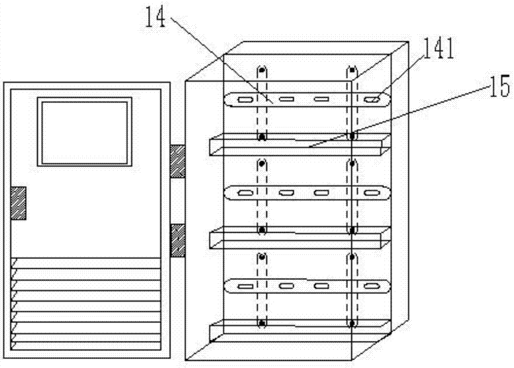
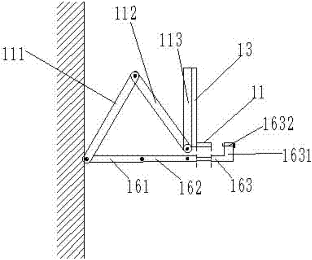
[0032] Embodiment 1: An automated electrical control cabinet, including a cabinet body and a cabinet door, the cabinet door is a side-opening cabinet door, the cabinet body includes a back wall and a side wall, the back wall and the side wall are integrally formed, and the control cabinet is also provided There is a movable back panel, which is parallel to the back wall and is movably set inside the cabinet. The height of the movable back panel is equal to the height of the back wall, and the width of the movable back panel is equal to the width of the back wall. The movable back panel includes multiple Installation area 1, multiple installation areas 1 are arranged in parallel, and the widths of multiple installation areas 1 are equal. The installation area 1 includes a movable bracket, a panel 13, a mounting bar 14 and a threading frame 15. One end of the movable bracket is fixedly arranged on the back wall, and the other end is connected to the panel 13, and the mounting bar ...

Embodiment 2

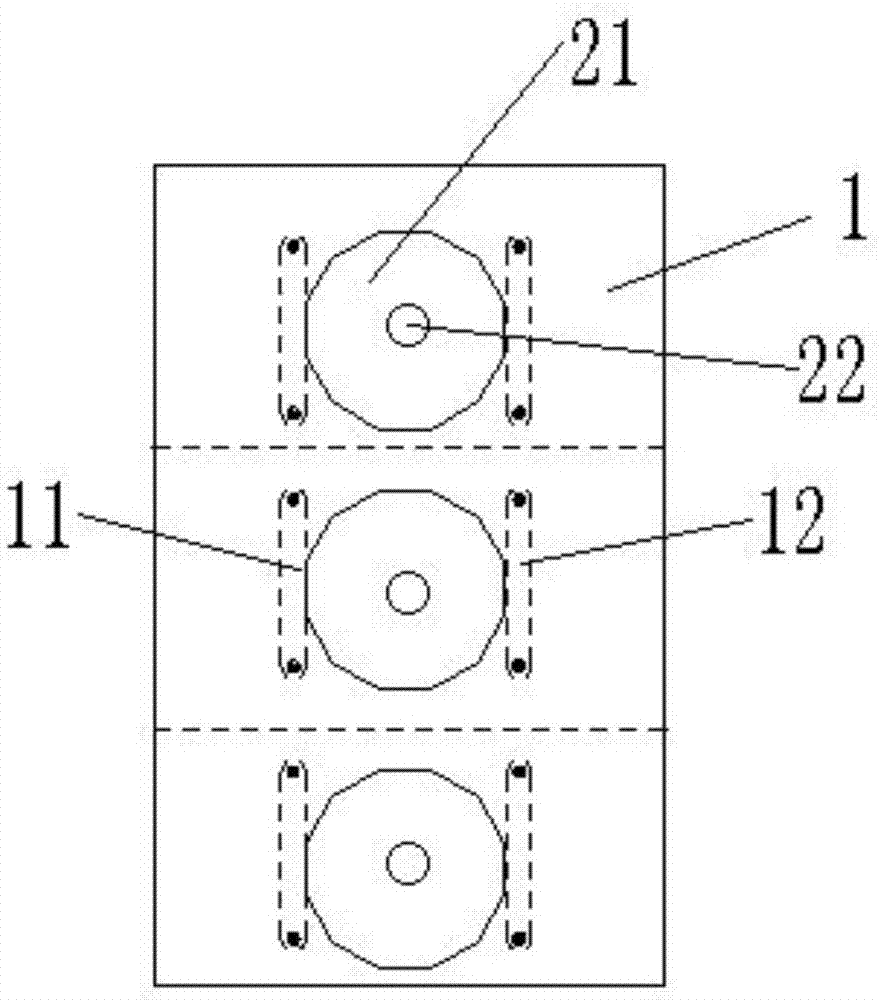
[0034] Embodiment 2: On the basis of embodiment 1, a safety protection device is provided between a plurality of the installation areas 1 and the back wall, the safety protection device is connected to the mobile back plate, and the safety protection device abuts against the back wall . The safety protection device includes an airbag 21, a piston 22, an inflation column 23 and a closed port 24. The piston 22 is sleeved in the inflation column 23 and is connected to the panel 13 at one end, and the other end is connected to the airbag 21 through the closed port 24. The airbag 21 is provided with a plurality of micropores, and the plurality of micropores are recessed inward. The airtight opening 24 is a conical opening, the small end of the conical opening is connected to the airbag 21, a small ball 241 is arranged in the airtight opening 24, and the small ball 241 is connected to the piston 22. The diameter of the small ball 241 is larger than the diameter of the small end of t...


PUM


Abstract

The invention provides an automatic electrical control cabinet. The automatic electrical control cabinet comprises a cabinet body and a cabinet door, the cabinet door is a side-opening cabinet door, the cabinet body comprises a back wall and sidewalls, and the back wall and the sidewalls are integrally moulded. The control cabinet is also provided with a mobile backboard, the mobile backboard is parallel to the back wall and is movably arranged in the cabinet body, the height of the mobile backboard is equal to that of the back wall, the width of the mobile backboard is equal to that of the back wall, the mobile backboard comprises a plurality of mounting zones which are arranged in parallel, and the width of the plurality of mounting zones is equal. A safety protection device is arranged between the plurality of mounting zones and the back wall, the safety protection device is connected with the mobile backboard, and the safety protection device abuts against the back wall. According to the invention, each mounting zone can be individually extracted for installation and maintenance, the problem that the space of the electrical control cabinet is relatively small, and the electrical control cabinet is not liable to maintain is solved, and the installation and maintenance efficiency is greatly improved.

Description

Technical field [0001] The invention relates to the technical field of electrical equipment structure design, and in particular to an automated electrical control cabinet. Background technique [0002] The electrical control cabinet is mainly used for electrical operation and control of the mechanical equipment on site. There are usually switches, relays, PLCs or power supplies. Due to its higher importance, the higher the requirements, the higher the need for regular For maintenance and overhaul, workers need to frequently change wires and connections from the outlet terminals in the electrical control cabinet to various devices on site. According to the technical standard requirements of the electrical control cabinet, the outlet terminals are generally fixedly arranged at the bottom of the lower end of the electrical control cabinet, and the electrical control cabinet is installed and fixed on the ground, so that the on-site staff are all connected when wiring in the electrica...

Claims


Application Information

Patent Timeline
Patent Type & Authority Applications(China)
IPC IPC(8): H05K5/02H05K7/14H05K7/20
CPCH05K5/0217H05K7/1401H05K7/20136
Inventor 陈子国
Owner 陈子国
Why Eureka
Try Eureka