Gas turbine engine

a technology of gas turbine engine and engine exhaust, which is applied in the direction of machines/engines, efficient propulsion technologies, light and heating apparatus, etc., can solve the problems of increasing sfc, significantly less power produced, and particularly pronounced problems, so as to reduce the formation of vapour trails, increase the exhaust temperature of the engine, and increase the exhaust of the engine

Active Publication Date: 2015-10-15
ROLLS ROYCE PLC
View PDF7 Cites 35 Cited by
  • Summary
  • Abstract
  • Description
  • Claims
  • Application Information

AI Technical Summary

Benefits of technology

[0015]It has been surprisingly found by the inventor that the above arrangement results in a gas turbine engine having improved (i.e. flat) SFC under a wide range of off design conditions (thrusts), and can result in over 3% lower fuel burn for a typical flight cycle compared to a comparable single combustor gas turbine engine. This is due to a significant reduction in engine weight together with a lower SFC.
[0022]The first combustor may comprise a lean burn combustor, and may comprise a pre-mixed combustion combustor. Advantageously, since the first combustor can be operated at substantially constant exit temperatures during most operating conditions, a lean burn combustor can be more easily implemented without the use of a stabilising diffusion flame. This may result in lower nitrous oxide (NOx) emissions. The second combustor may also comprise a lean burn or diffusion flame combustor.
[0023]At least one of the first combustor and second combustor may comprise a cooling system configured to provide cooling air to the respective combustor from one of the compressors. The cooling air for the second combustor may be delivered from a compressor stage upstream of the compressor stage from which the cooling air for the first combustor is delivered. Advantageously, thermodynamic losses from cooling the second combustor are minimised.
[0028]The inventor has discovered that the present invention provides reduced SFC compared to other methods of operation, when the first combustor is operated at a constant combustor exit temperature. The invention can provide for varied thrust by regulation of fuel flow to the second combustor.
[0031]This method of operation has been found to result in an increased exhaust temperature from the engine. It is thought that this increased engine exhaust temperature can reduce the formation of vapour trails, and so reduce the climate change impact of the engine.
[0035]Advantageously, the engine is operated in accordance with a high efficiency operating method when vapour trail forming conditions are not detected, and a lower efficiency (but potentially less environmentally damaging) mode when vapour trails are detected. Consequently, the invention provides improved environmental performance by reducing carbon emissions, while also reducing vapour trail formation.

Problems solved by technology

However, previous studies have only found arrangements which can be expected to have increased SFC compared to gas turbines having conventional combustors.
This problem is particularly pronounced in gas turbine engines which are required to operate efficiently across a wide range of thrust / power levels.
At power levels below this design point (so called “off design conditions”), power is produced significantly less efficiently.
However, such operation is not generally practical in multi-spool gas turbines having several compressors driven by separate turbines, as this would require variable geometry turbines or exhaust.
However, such isothermal expansions are inefficient and such cycles require the use of a recuperator (i.e. a device to transfer heat from the exhaust to the compressor outlet) to overcome the inefficiency of such isothermal cycles.

Method used


Image

  • Gas turbine engine
  • Gas turbine engine
  • Gas turbine engine

Examples


Embodiment Construction

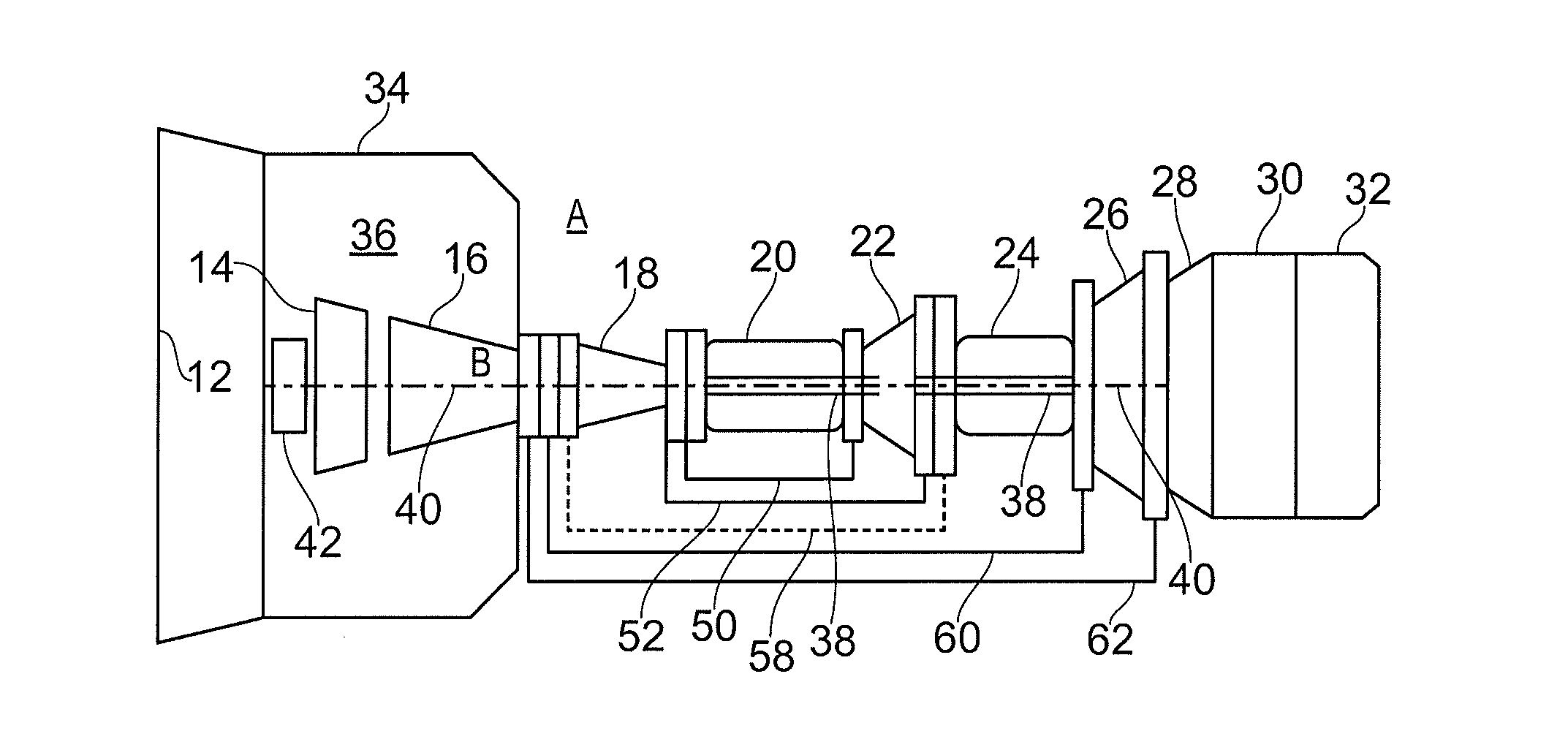
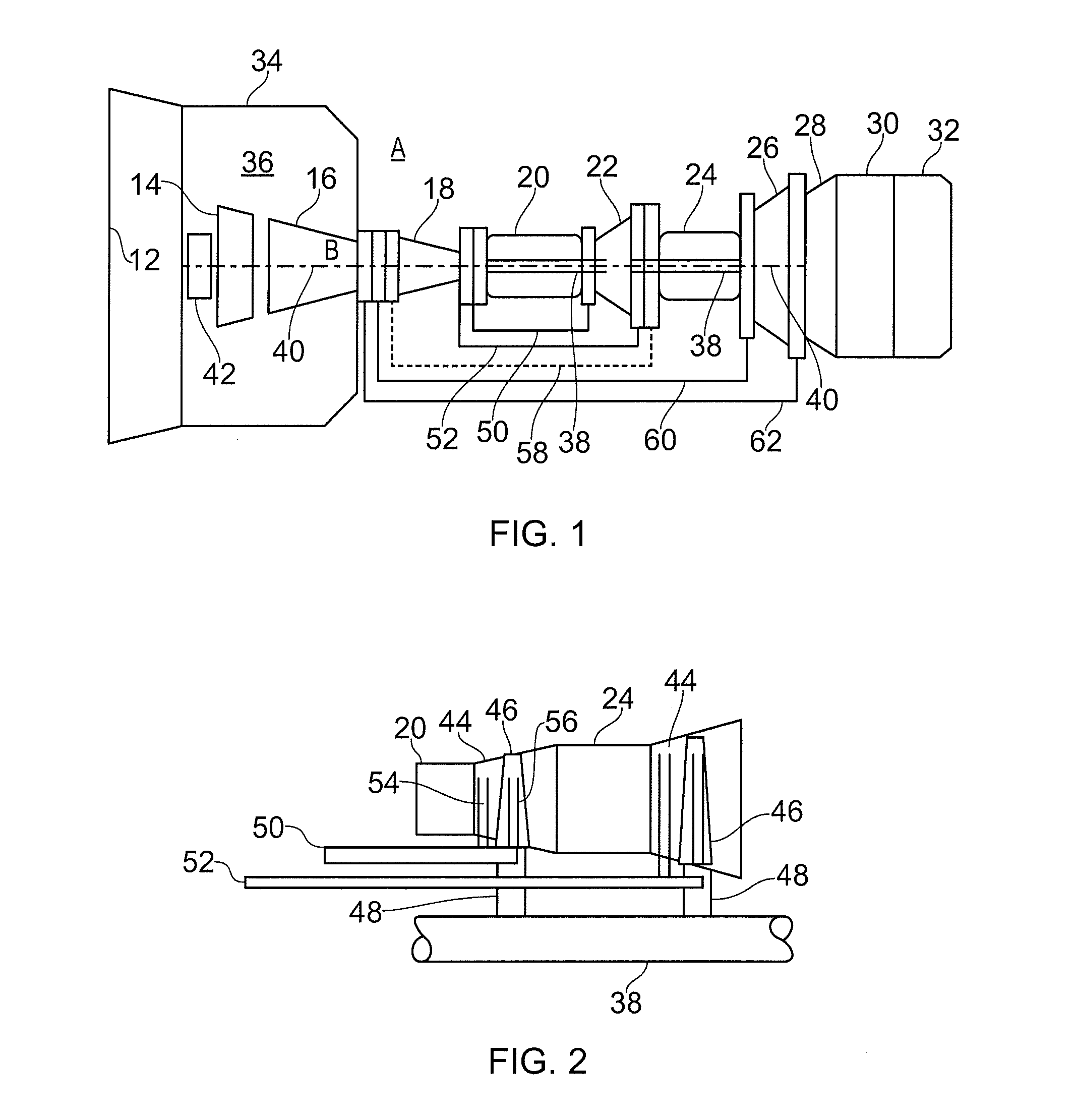
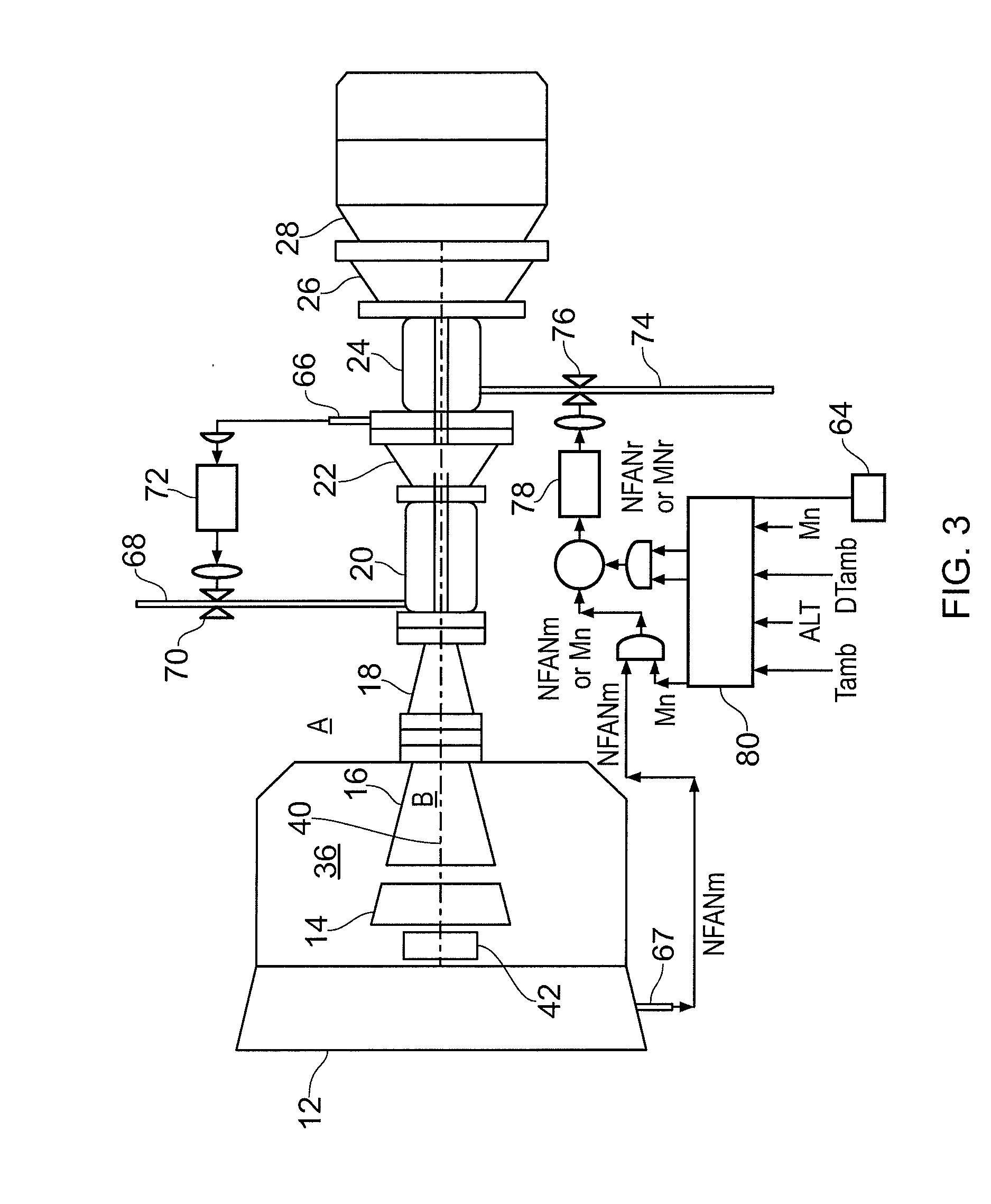
[0043]FIGS. 1 to 4 show a gas turbine engine 10, methods of controlling the engine 10, and a T-S diagram showing the thermodynamic cycle of the engine 10.

[0044]The gas turbine engine 10 comprises an air intake and a propulsive fan 12 that generates two airflows A and B. The gas turbine engine 10 comprises, in axial flow A, a core comprising a booster compressor 14, a high pressure compressor 16, 18, a first combustor 20, a high pressure turbine comprising a first turbine stage 22, a second combustor 24, a second turbine stage 26 of the high pressure turbine, a low pressure turbine 28, an optional afterburner 30, and an exhaust nozzle 28. A fan housing 34 surrounds the core and fan 14 and defines, in axial flow B, a bypass duct 36.

[0045]The first and second stages 22, 26 of the high pressure turbine are coupled to the high pressure compressor 16, 18 by a first shaft 36. The low pressure turbine 28 is coupled to the booster compressor 14 and fan 12 by a further shaft 40 arranged coaxi...


PUM


Abstract

A gas turbine engine. The engine includes a first compressor coupled to a first turbine by a first shaft, the first turbine having first and second turbine stages. A first combustor is provided downstream of the first compressor and upstream of the first stage of the first turbine. A second combustor is provided downstream of the first stage of the first turbine, and upstream of the second stage of the first turbine. A further turbine is provided downstream of the first turbine, and is coupled to a further compressor by a further shaft.

Description

FIELD OF THE INVENTION[0001]The present invention relates to a gas turbine engine and a method of operating a gas turbine engine. Particularly, though not exclusively, the invention relates to gas turbine engines for use in aircraft.BACKGROUND TO THE INVENTION[0002]There is a continual need to decrease the fuel consumption of aircraft gas turbine engines (for example, in terms of Specific Fuel Consumption (SFC)), in order to save operating costs, and to reduce their environmental impact due to carbon emissions and nitrous oxide (NOx). Another requirement is to reduce “contrails” formed by condensing water vapour produced by aircraft engines when operating at high altitude in some circumstances, again in order to reduce the impact of the aircraft on the environment.[0003]Gas turbine engines comprising “sequential” combustors have been proposed for use in electricity production. Examples include the GT24 gas turbine engine produced by Alstom™. In such gas turbine engines, a second com...

Claims


Application Information

Patent Timeline
Patent Type & Authority Applications(United States)
IPC IPC(8): F02C3/14F02C7/12F02C3/06
CPCF02C3/14F02C3/064F05D2240/24F05D2220/323F05D2240/35F02C7/12F02K3/06F02C6/003F02C9/28F05D2270/082F02K3/08Y02T50/60F23R2900/03341
Inventor RAZAK, AHMAD
Owner ROLLS ROYCE PLC
Why Eureka
Try Eureka