
Reduced reel motor disturbances in a tape drive system

Active Publication Date: 2015-10-15
IBM CORP
View PDF2 Cites 9 Cited by
  • Summary
  • Abstract
  • Description
  • Claims
  • Application Information

AI Technical Summary

Benefits of technology

This patent describes an apparatus and system for converting kinetic energy into heat using a damping layer made of a material. The technical effect is the efficient dissipation of excess energy, which leads to improved performance and reliability in magnetic data storage systems.

Problems solved by technology

However, the development of small footprint, higher performance tape drive systems has created various problems in the design of a tape head assembly for use in such systems.

Method used


Image

  • Reduced reel motor disturbances in a tape drive system
  • Reduced reel motor disturbances in a tape drive system
  • Reduced reel motor disturbances in a tape drive system

Examples


Embodiment Construction

[0023]The following description is made for the purpose of illustrating the general principles of the present invention and is not meant to limit the inventive concepts claimed herein. Further, particular features described herein can be used in combination with other described features in each of the various possible combinations and permutations.

[0024]Unless otherwise specifically defined herein, all terms are to be given their broadest possible interpretation including meanings implied from the specification as well as meanings understood by those skilled in the art and / or as defined in dictionaries, treatises, etc.

[0025]It must also be noted that, as used in the specification and the appended claims, the singular forms “a,”“an” and “the” include plural referents unless otherwise specified. Furthermore, it should be noted that, as used herein, the term “about” with reference to some stated value refers to the stated value±10% of said value.

[0026]The following description disclose...


PUM


Abstract

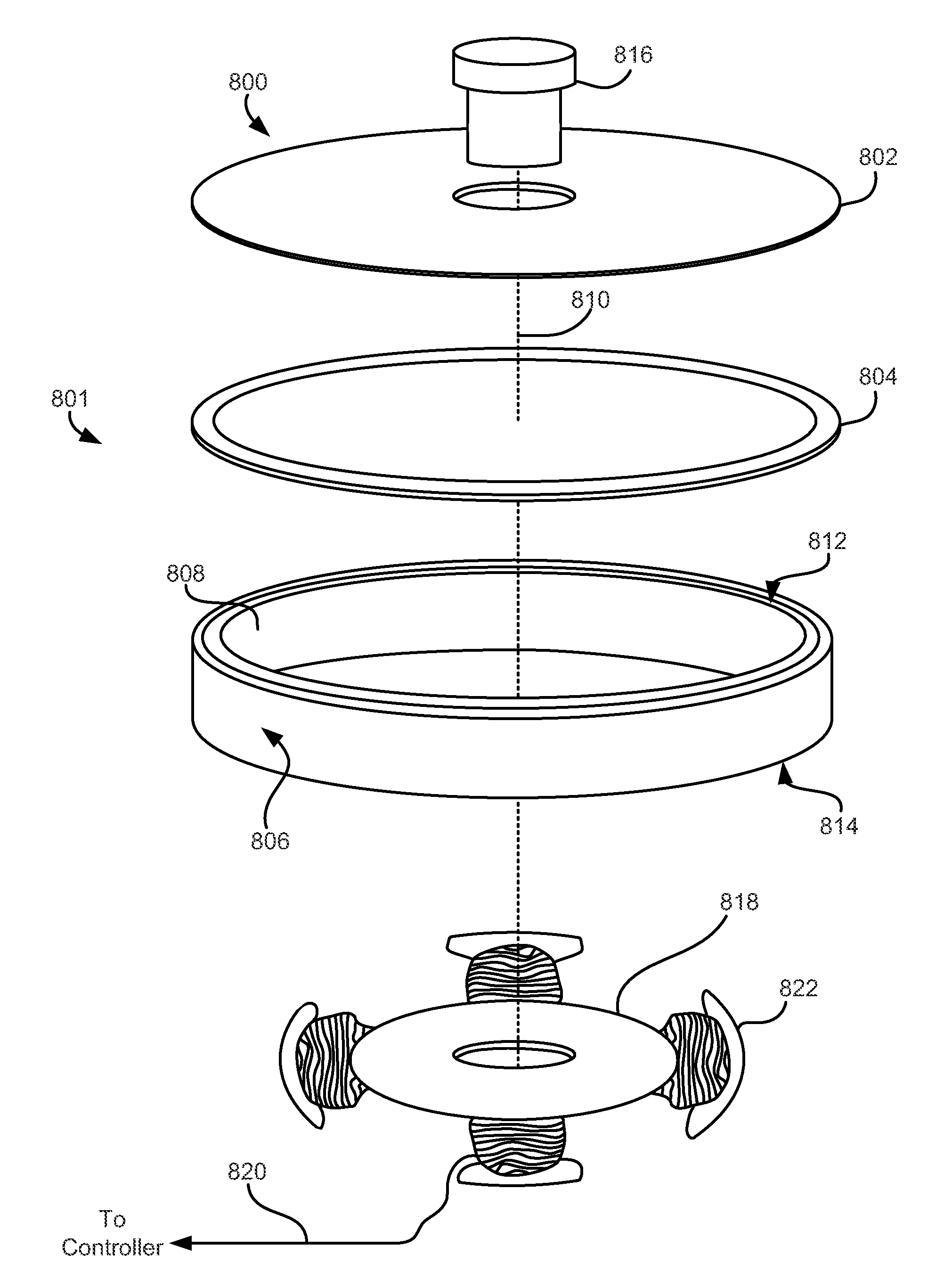
An apparatus according to one embodiment includes a motor having: a rotor, a magnet, and a damping layer positioned between the rotor and the magnet. The damping layer is constructed of a material characterized by converting kinetic energy into heat.

Description

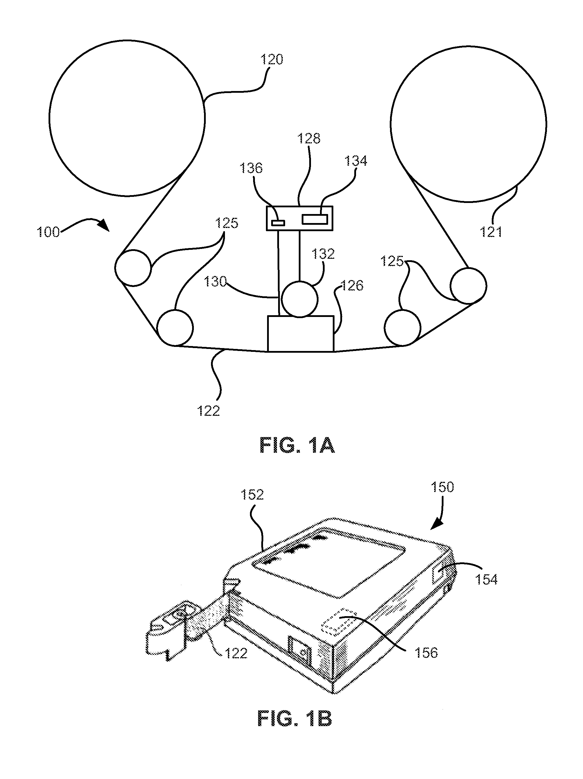
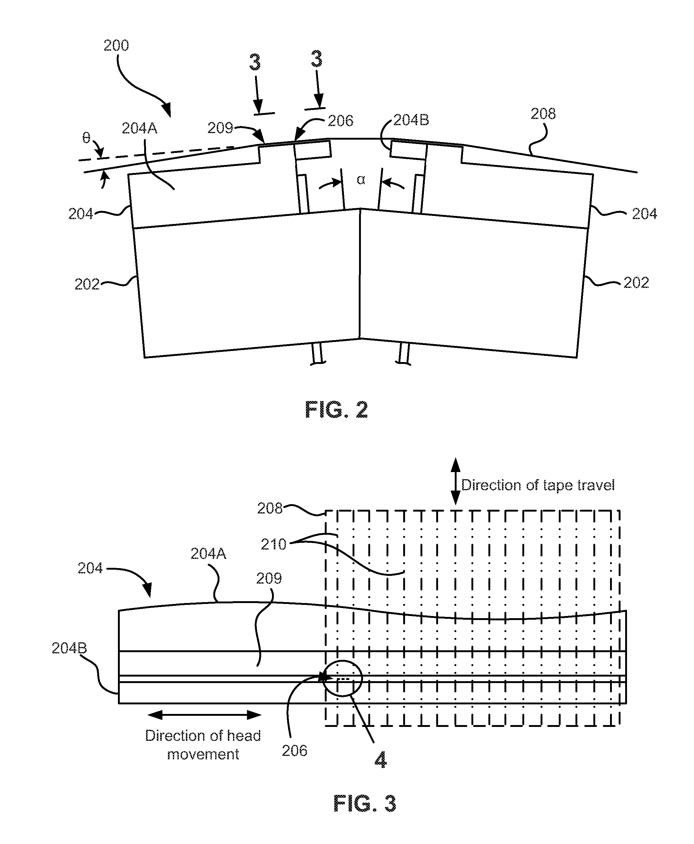
BACKGROUND[0001]The present invention relates to data storage systems, and more particularly, this invention relates to tape drive motors having reduced runtime disturbances.[0002]In magnetic storage systems, magnetic transducers read data from and write data onto magnetic recording media. Data is written on the magnetic recording media by moving a magnetic recording transducer to a position over the media where the data is to be stored. The magnetic recording transducer then generates a magnetic field, which encodes the data into the magnetic media. Data is read from the media by similarly positioning the magnetic read transducer and then sensing the magnetic field of the magnetic media. Read and write operations may be independently synchronized with the movement of the media to ensure that the data can be read from and written to the desired location on the media.[0003]An important and continuing goal in the data storage industry is that of increasing the density of data stored o...

Claims


Application Information

Patent Timeline
IPC IPC(8): G11B19/20H02K3/20
CPCH02K3/20G11B19/2009H02K1/30G11B5/00813G11B15/18G11B15/26H02K1/2733
Inventor HARPER, DAVID H. F.ROTHUIZEN, HUGO E.
Owner IBM CORP
Learn More