Substrate processing apparatus

a technology of substrate and processing apparatus, which is applied in the direction of electrolysis components, vacuum evaporation coatings, coatings, etc., can solve the problems of difficult maintenance of the apparatus, and achieve the effect of high-quality thin films and suppressing a pressure change in the process spa

Active Publication Date: 2015-10-15
CANON ANELVA CORP
View PDF4 Cites 6 Cited by
  • Summary
  • Abstract
  • Description
  • Claims
  • Application Information

AI Technical Summary

Benefits of technology

[0012]According to the present invention, it is possible to provide a technique capable of suppressing a pressure change in a process space when a substrate holder is moved and advantageous in depositing a high-quality thin film.

Problems solved by technology

In a sputtering apparatus, if a thin film is formed on the inner wall of the process chamber, maintenance of the apparatus becomes difficult.

Method used


Image

  • Substrate processing apparatus
  • Substrate processing apparatus
  • Substrate processing apparatus

Examples


first embodiment

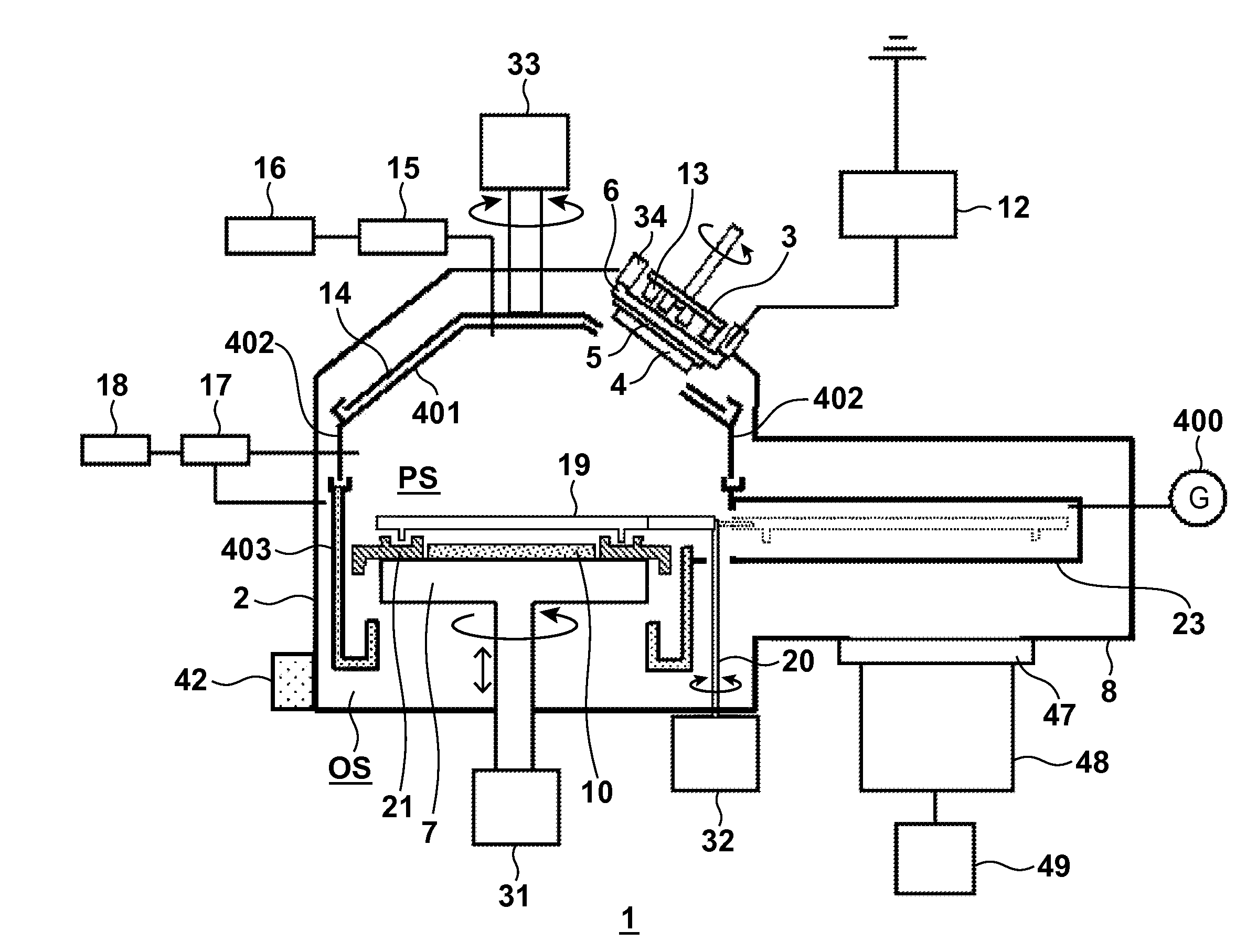
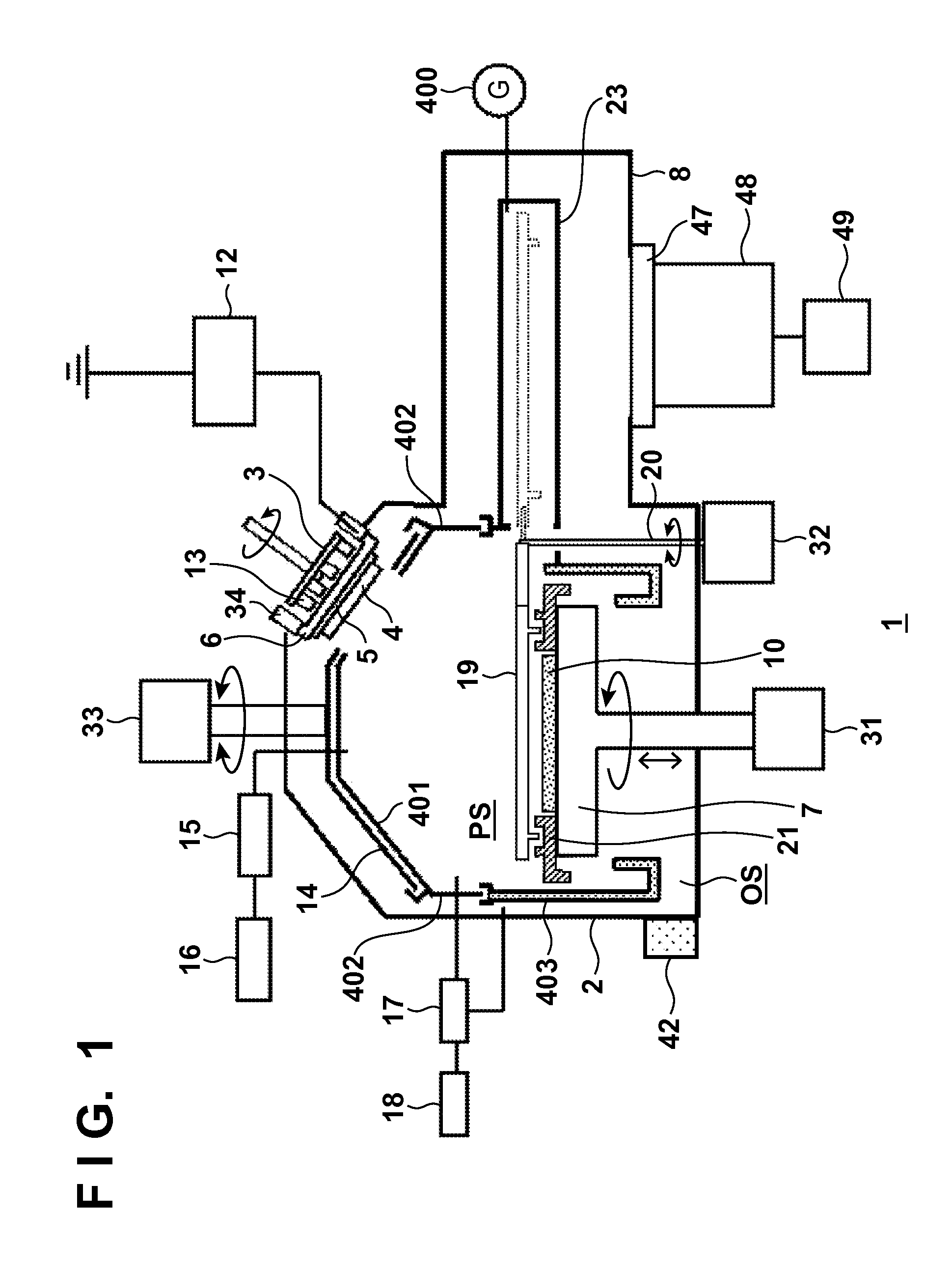
[0044]Shields in the neighborhood of a substrate holder 7 will be described with reference to FIG. 2. A substrate 10 is arranged on the substrate holder 7. In addition, a cover ring 21 is placed at the peripheral portion of the substrate holder. A shield 403 is attached to a process chamber 2 while forming a predetermined gap with respect to the cover ring 21. The substrate holder 7 can move in a direction perpendicular to the substrate holding surface to adjust the TS distance. Along with this movement, the cover ring 21 also moves together with the substrate holder 7. On the other hand, since the shield 403 is fixed to the process chamber 2, the position of the shield 403 does not change along with the movement of the substrate holder 7.

[0045]A process gas introduced into the vacuum chamber 2 is exhausted from a process space PS or introduced into the process space PS via the gap between the shield 403 and the cover ring 21. An index quantitatively representing the easiness of exh...

second embodiment

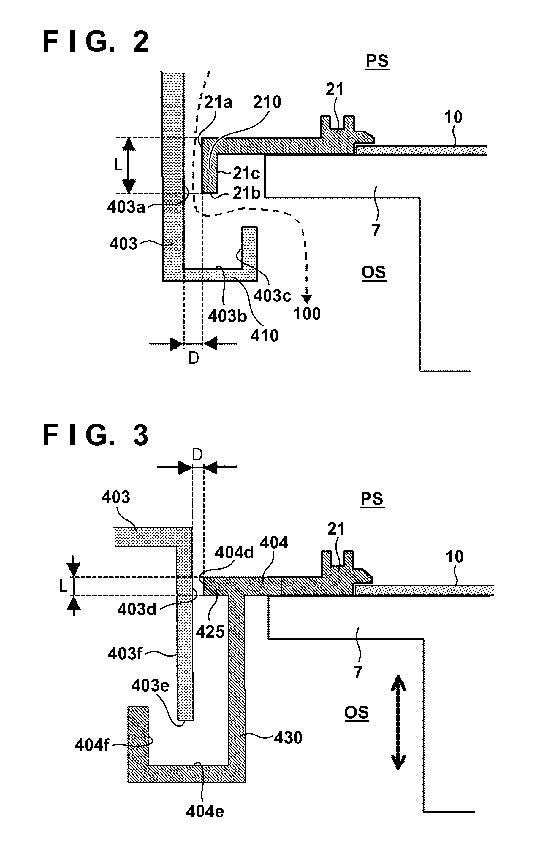
[0053]FIG. 3 shows the second embodiment of the present invention. In the second embodiment, a shield 404 is provided outside a cover ring 21, and an exhaust path is formed by the shield 404 and a shield 403. If the cover ring 21 and the shield 404 are separate members, restrictions in designing the cover ring 21 can be reduced. For example, the shield 404 and the cover ring 21 can be manufactured using different materials. The cover ring 21 and the shield 404 may be integrated, as a matter of course.

[0054]In the second embodiment, the distance between an outer side surface 403d of the shield 403 and a surface 404d of a projecting portion of the shield 404, which projects to the side of the shield 403, corresponds to a minimum gap D out of the gap formed between the shields 403 and 404. A length L of the minimum gap portion forming the minimum gap D affects the conductance most. However, even if a substrate holder 7 moves in the vertical direction, the length L of the minimum gap po...

third embodiment

[0062]FIG. 5 shows the third embodiment of the present invention. In the third embodiment, a shield 404 bends so as to surround the distal end of a shield 403, and the distal end of the shield 404 further bends toward the shield 403. The apparatus is configured such that the gap between a surface 404h of the bending portion facing the shield 403 and a surface 403h of the shield 403 facing the bending portion becomes a minimum gap D.

[0063]The effect of the third embodiment will be described with reference to FIGS. 6A and 6B. Each of FIGS. 6A and 6B shows a state in which a substrate holder 7 is moved downward as much as possible within the range where a linear path from the center of a process space PS (or the central axis of the substrate holder 7) to an outer space OS does not exist. Members other than the members forming the main exhaust path are not illustrated in FIGS. 6A and 6B.

[0064]Before forming a film on a substrate by sputtering, to suppress gas emission from the surfaces ...


PUM

PropertyMeasurementUnit
lengthaaaaaaaaaa
sizeaaaaaaaaaa
thicknessaaaaaaaaaa

Abstract

An apparatus includes a process chamber, a substrate holder arranged in the process chamber, a first shield provided on the peripheral portion of the substrate holder, and a second shield provided inside the process chamber. The internal space of the process chamber is partitioned into an outer space and a process space to process the substrate, by at least the first shield, the second shield, and the substrate holder. The substrate holder can be driven along a driving direction perpendicular to a substrate holding surface. The length, in a direction parallel to the driving direction, of a minimum gap portion having a minimum size in a direction perpendicular to the driving direction between the first and second shields does not change even if the substrate holder is driven in the driving direction.

Description

[0001]This application is a continuation of International Patent Application No. PCT / JP2013 / 006997 filed on Nov. 28, 2013, and claims priority to Japanese Patent Application No. 2012-282467 filed on Dec. 26, 2012, the entire content of both of which is incorporated herein by reference.TECHNICAL FIELD[0002]The present invention relates to a substrate processing apparatus.BACKGROUND ART[0003]In a sputtering apparatus, if a thin film is formed on the inner wall of the process chamber, maintenance of the apparatus becomes difficult. Hence, an interchangeable protection shield is placed in the process chamber to protect the inner wall. The distance between a target and a substrate (to be referred to as a TS distance hereinafter) is known to affect the evenness of the thickness or quality of a formed film. In addition, the film thickness or film thickness distribution tends to gradually degrade as the target is gradually sputtered, and erosion progresses, as is known. Concerning these phe...

Claims


Application Information

Patent Timeline
Patent Type & Authority Applications(United States)
IPC IPC(8): H01J37/34
CPCH01J37/3441C23C14/34H01J37/32477H01J37/32733H01J37/3405H01J37/347H01J37/32715C23C14/3492C23C14/50C23C14/54
Inventor SHIMANE, YOSHIMITSUUCHINO, SATOSHIAKIYAMA, SUSUMUMATSUO, KAZUAKIYAMAGUCHI, NOBUO
Owner CANON ANELVA CORP
Why Eureka
Try Eureka