Charging connector

Inactive Publication Date: 2015-10-15
YAZAKI CORP
View PDF22 Cites 18 Cited by
  • Summary
  • Abstract
  • Description
  • Claims
  • Application Information

AI Technical Summary

Benefits of technology

[0013]According to the above-mentioned constitution, the intrusion of water into the connector body in the inside of the exterior case is prevented by the seal member and hence, waterproofing of the terminals in the inside of the connector body can be realized. The seal member is a single part which is interposed between two case split bodies, and is also assembled between the exterior case and the connector body as well as between the exteri

Problems solved by technology

The rubber plugs are expensive, and it is necessary to provide the rubber plugs the number of which corresponds to the number of terminals.
Accordingly, a cost of parts, an a

Method used


Image

  • Charging connector
  • Charging connector
  • Charging connector

Examples


Embodiment Construction

[0021]An embodiment of the present invention will be described hereinafter with reference to the drawings.

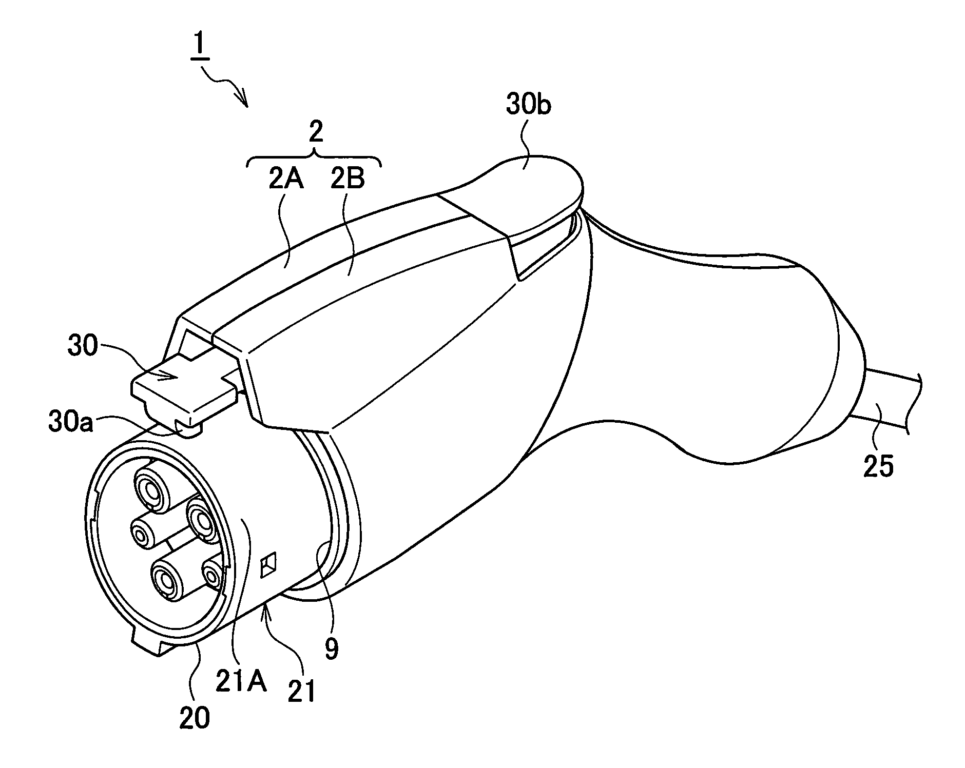
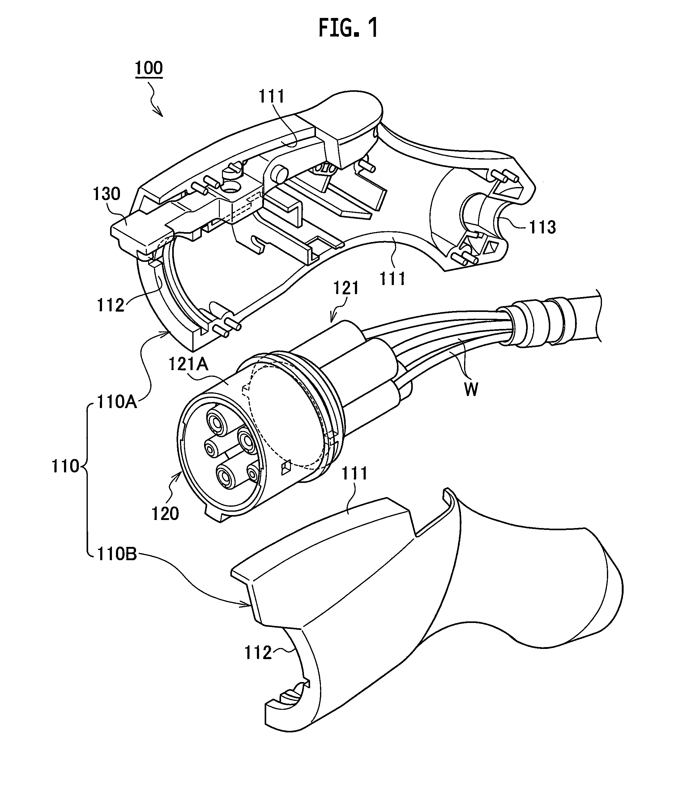
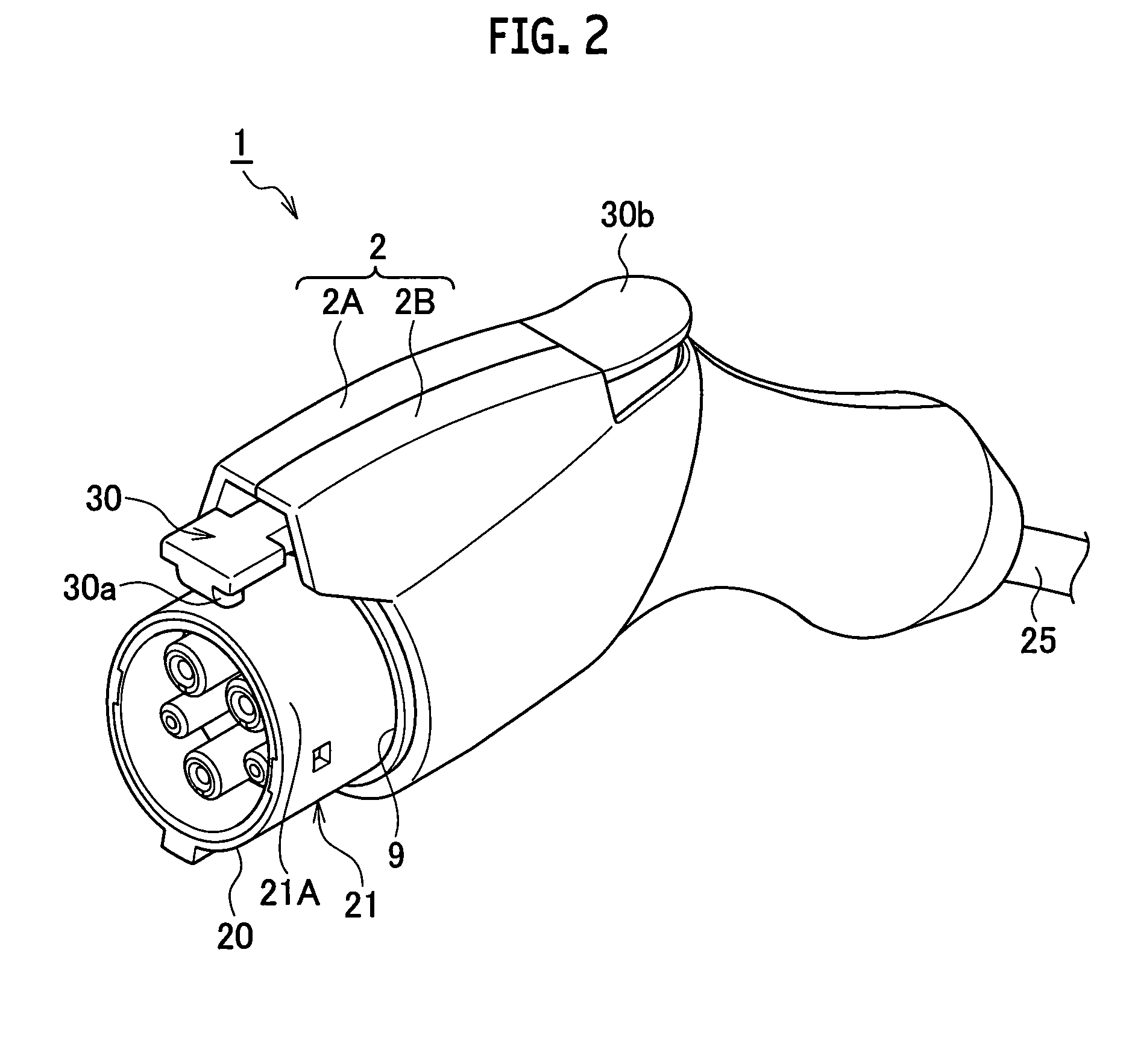
[0022]FIG. 2 to FIG. 6B show one embodiment of the present invention. As shown in FIG. 2 to FIG. 4, a charging connector 1 includes: an exterior case 2; a connector body 20 which is housed in the inside of the exterior case 2; a lock arm 30 which is arranged in the inside of the exterior case 2; a micro switch 31 which is turned on or off by the lock arm 30; and a seal member 40.

[0023]The exterior case 2 is constituted of two case split bodies 2A, 2B which are assembled to each other. An abutting surface 3 is formed on the substantially whole outer periphery of each case split body 2A, 2B. Each case split body 2A, 2B has a lock arm housing chamber 4 and a connector housing chamber 5 therein, and these housing portions 4, 5 are partitioned from each other by an inner partition wall 6. A distal end surface of the inner partition wall 6 forms an abutting surface 7. A seal holding g...


PUM


Abstract

A seal member (40) is formed of an integral body including a case split surface seal portion (41) arranged along whole circumferences of abutting surfaces (3, 7) surrounding a portion of a connector body (20) housed inside an exterior case (2) and interposed between the abutting surfaces (3, 7) of two case split bodies (2A, 2B), a connector body seal portion (42) arranged along a whole circumference of a connector fitting portion projecting hole (9) and interposed between the exterior case (2) and the connector body (20), and an electric wire seal portion (43) arranged along a whole circumference of an electric wire pullout hole (10) and interposed between the exterior case (2) and an electric wire (W1) pulled out from the connector body (20) and led outside the exterior case (2) through the electric wire pullout hole (10).

Description

TECHNICAL FIELD[0001]The present invention relates to a charging connector used at the time of charging a battery mounted on a vehicle such as an electric vehicle or a hybrid electric vehicle.BACKGROUND ART[0002]A charging connector has been used for charging a battery mounted on a vehicle such as an electric vehicle (EV) or a hybrid electric vehicle (HEV) (see Patent Literature 1). An example relating to this type of charging connector is described by reference to FIG. 1.[0003]As shown in FIG. 1, a charging connector 100 includes an exterior case 110, a connector body 120 arranged in the inside of the exterior case 110, and a lock arm 130 arranged in the inside of the exterior case 110.[0004]The exterior case 110 is formed of two case split bodies 110A, 110B. The respective case split bodies 110A, 110B have abutting surfaces 111 which are made to come into contact with each other, and the exterior case 110 is formed by making the abutting surfaces 111 come into contact with each ot...

Claims


Application Information

Patent Timeline
IPC IPC(8): H01R13/52B60L11/18
CPCB60L11/1818H01R13/5202B60L53/16H01R13/516H01R13/5205H01R13/6275H01R2201/26Y02T90/14H01R13/5045H01R13/5219Y02T10/7072H01R13/701Y02T10/70
Inventor SAWADA, TSUTOMUYAMADA, NORIHISA
Owner YAZAKI CORP
Why Eureka
Try Eureka