Rotor for a rotary electric machine
- Summary
- Abstract
- Description
- Claims
- Application Information
AI Technical Summary
Benefits of technology
Problems solved by technology
Method used
Image

Examples
first embodiment
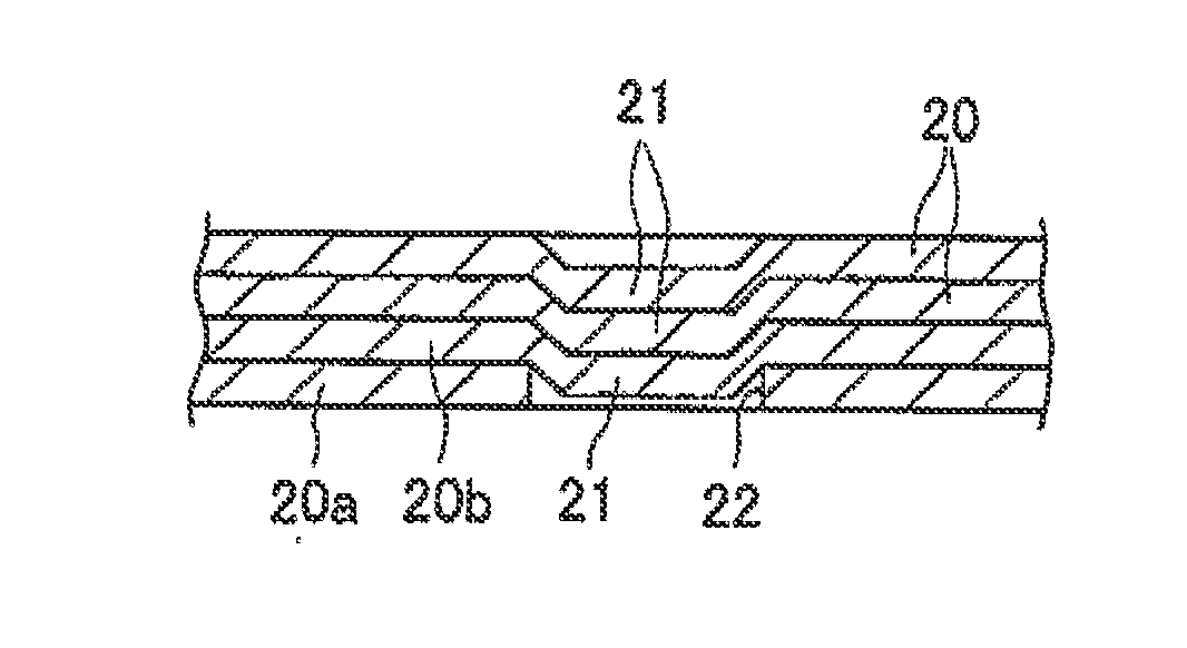
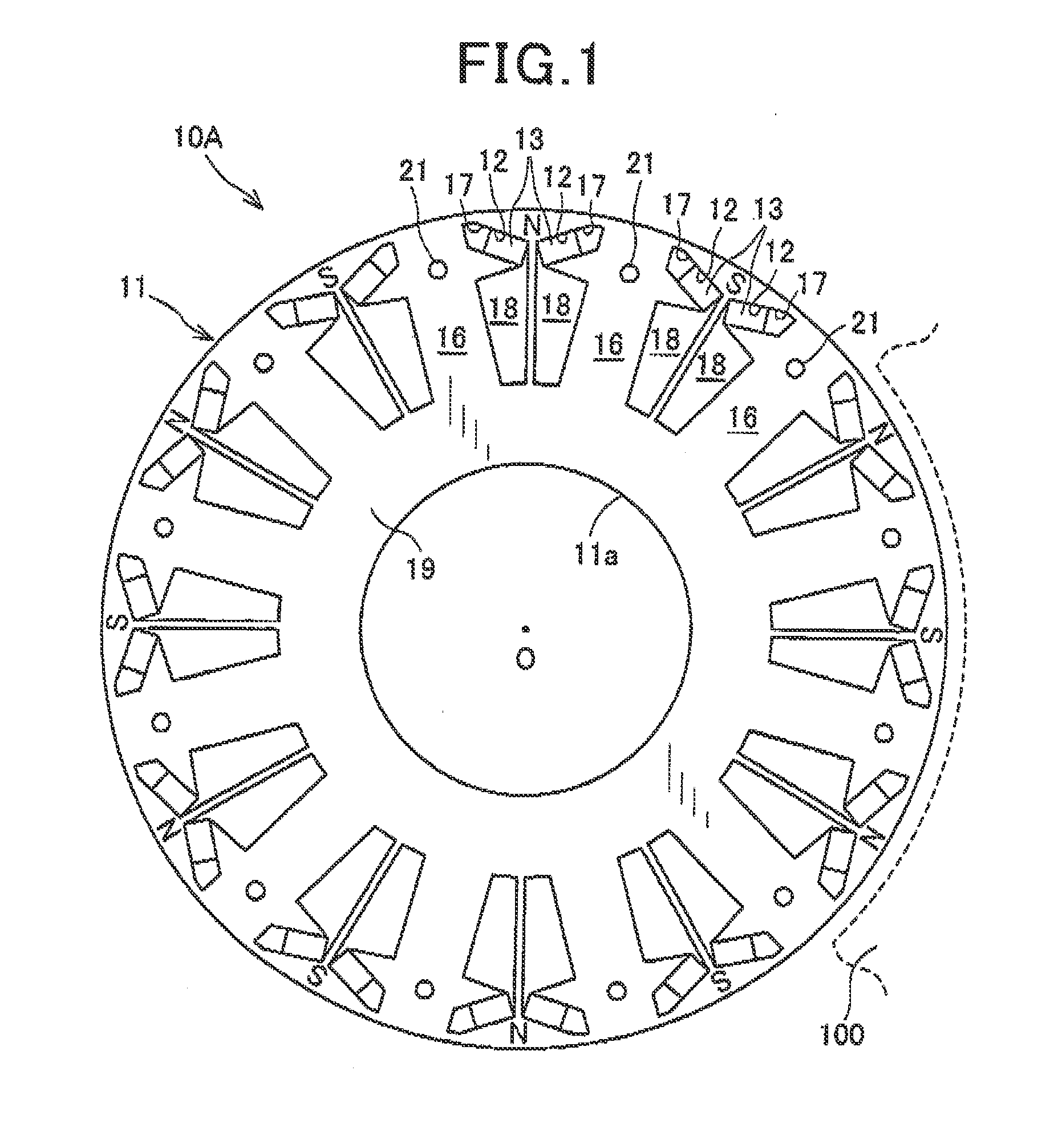
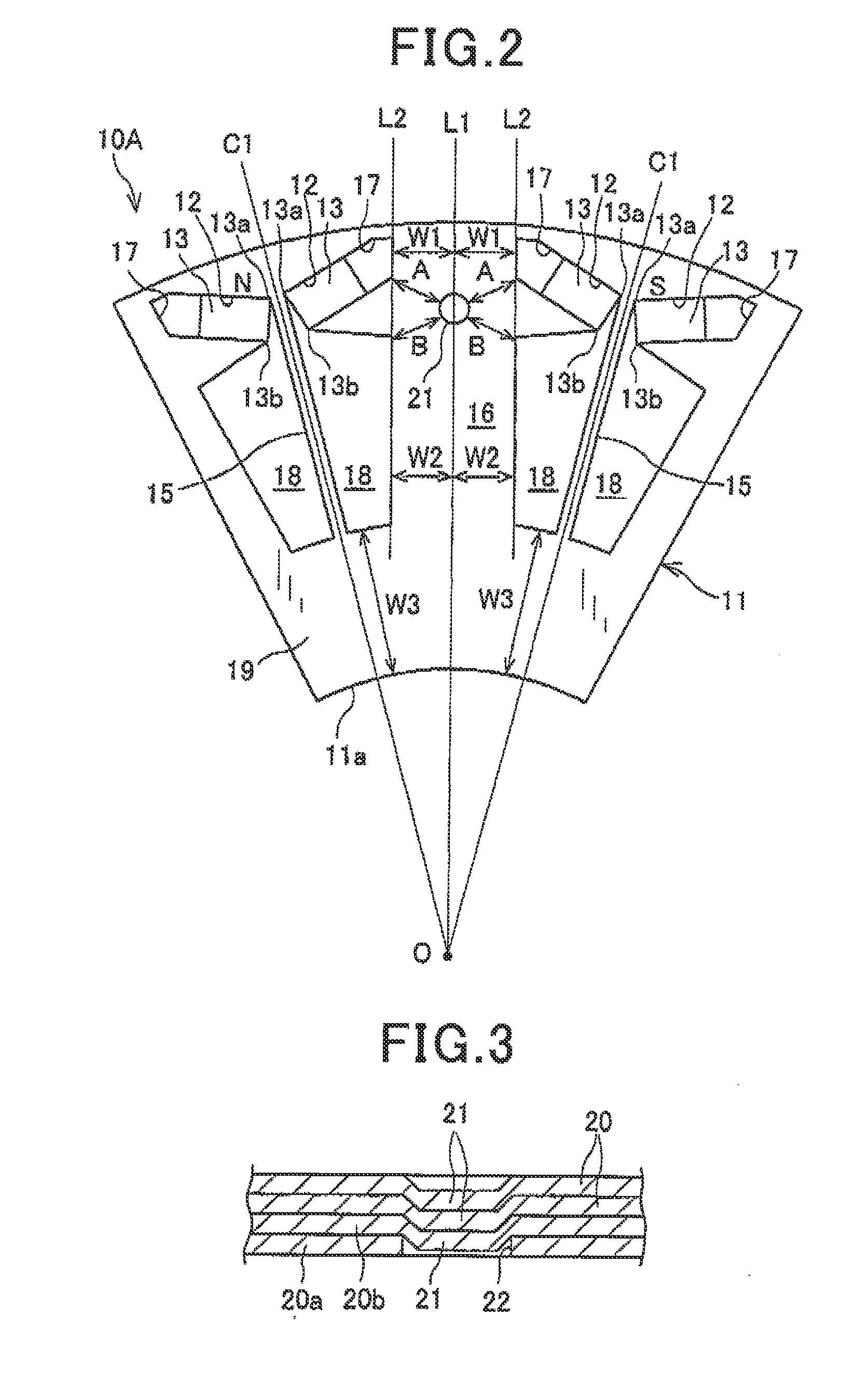
[0026]A rotor for a rotary electric machine according to the first embodiment is described with reference to FIGS. 1 to 3. A rotor 10A of the first embodiment is installed in a rotary electric machine (not shown) used as, for example, a motor for a vehicle. The rotor 10A is accommodated in a housing of the rotary electric machine. The rotor 10A is rotatably disposed along an inner circumference of a stator 100 (partially shown in FIG. 1) having a cylindrical shape. The rotary electric machine has a rotating shaft (not shown) whose both ends are rotatably supported on the housing via bearings. The rotor 10A of the first embodiment is fitted and fixed to the outer periphery of the rotating shaft.
[0027]The rotor 10A is disposed so as to be opposed to the stator 100 in the radial direction. The rotor 10A includes a rotor core 11, which has a plurality of magnet housing holes 12 arranged in the circumferential direction, and a plurality of magnets (permanent magnets) 13, which are buried...
second embodiment
[0043]As shown in FIGS. 4 and 5, in a rotor 10B for a rotary electric machine according to the second embodiment, only a shape of a crimped portion 21B fixing the laminated steel plates 20 configuring the rotor core 11 is different from that in the first embodiment. Hence, detailed explanations of members and configurations common to those of the first embodiment are omitted to explain different points and important points. Note that the same reference numerals as in the first embodiment denote the same parts.
[0044]As in the case of the first embodiment, the rotor core 11 of the second embodiment is provided with the magnet housing holes 12, the first flux barriers 17, and the second flux barriers 18 at predetermined positions. As shown in FIG. 4, the crimped portion 21B having an ellipse shape is provided in the q axis core portion 16 of the rotor core 11 so that the major axis of the ellipse is directed in the radial direction. That is, when viewed in the crimping direction, the c...
third embodiment
[0049]As shown in FIGS. 6 and 7, in a rotor 10C for a rotary electric machine according to the third embodiment, only a shape of a crimped portion 21C fixing the laminated steel plates 20 configuring the rotor core 11 is different from that in the first embodiment. Hence, detailed explanations of members and configurations common to those of the first embodiment are omitted to explain different points and important points. Note that the same reference numerals as in the first embodiment denote the same parts.
[0050]As in the case of the first embodiment, the rotor core 11 of the third embodiment is provided with the magnet housing holes 12, the first flux barriers 17, and the second flux barriers 18 at predetermined positions. As shown in FIG. 6, the crimped portion 21C having an ellipse shape is provided in the q axis core portion 16 of the rotor core 11 so that the major axis of the ellipse is directed in the circumferential direction. That Is, when viewed in the crimping direction...
PUM
 Abstract
Description
Claims
Application Information
 - Generate Ideas
- Intellectual Property
- Life Sciences
- Materials
- Tech Scout
- Unparalleled Data Quality
- Higher Quality Content
- 60% Fewer Hallucinations
Browse by: Latest US Patents, China's latest patents, Technical Efficacy Thesaurus, Application Domain, Technology Topic, Popular Technical Reports.
© 2025 PatSnap. All rights reserved.Legal|Privacy policy|Modern Slavery Act Transparency Statement|Sitemap|About US| Contact US: help@patsnap.com