Optical active cable and optical transmission system

a technology of optical transmission system and active cable, which is applied in the direction of transmission monitoring, electromagnetic transmission, electromagnetic transceivers, etc., can solve the problems of increasing the size of the optical module and the structure of the optical module may be complicated

Inactive Publication Date: 2015-10-15
HITACHI METALS LTD
View PDF11 Cites 6 Cited by
  • Summary
  • Abstract
  • Description
  • Claims
  • Application Information

AI Technical Summary

Benefits of technology

[0028]According to one embodiment of the invention, an optical active cable can be provided that can monitor the light intensity of a light emitted from a light emitting element without complicating the structure of optical module, as well as an optical transmission system using the optical cable.

Problems solved by technology

In the conventional method, where the light receiving element for monitoring is disposed in the optical module, there is a problem that the optical module may be complicated in structure and may increase in size.

Method used


Image

  • Optical active cable and optical transmission system
  • Optical active cable and optical transmission system
  • Optical active cable and optical transmission system

Examples


Embodiment Construction

[0034]Hereinafter, the embodiments according to the invention will be explained in accordance with the accompanying drawings.

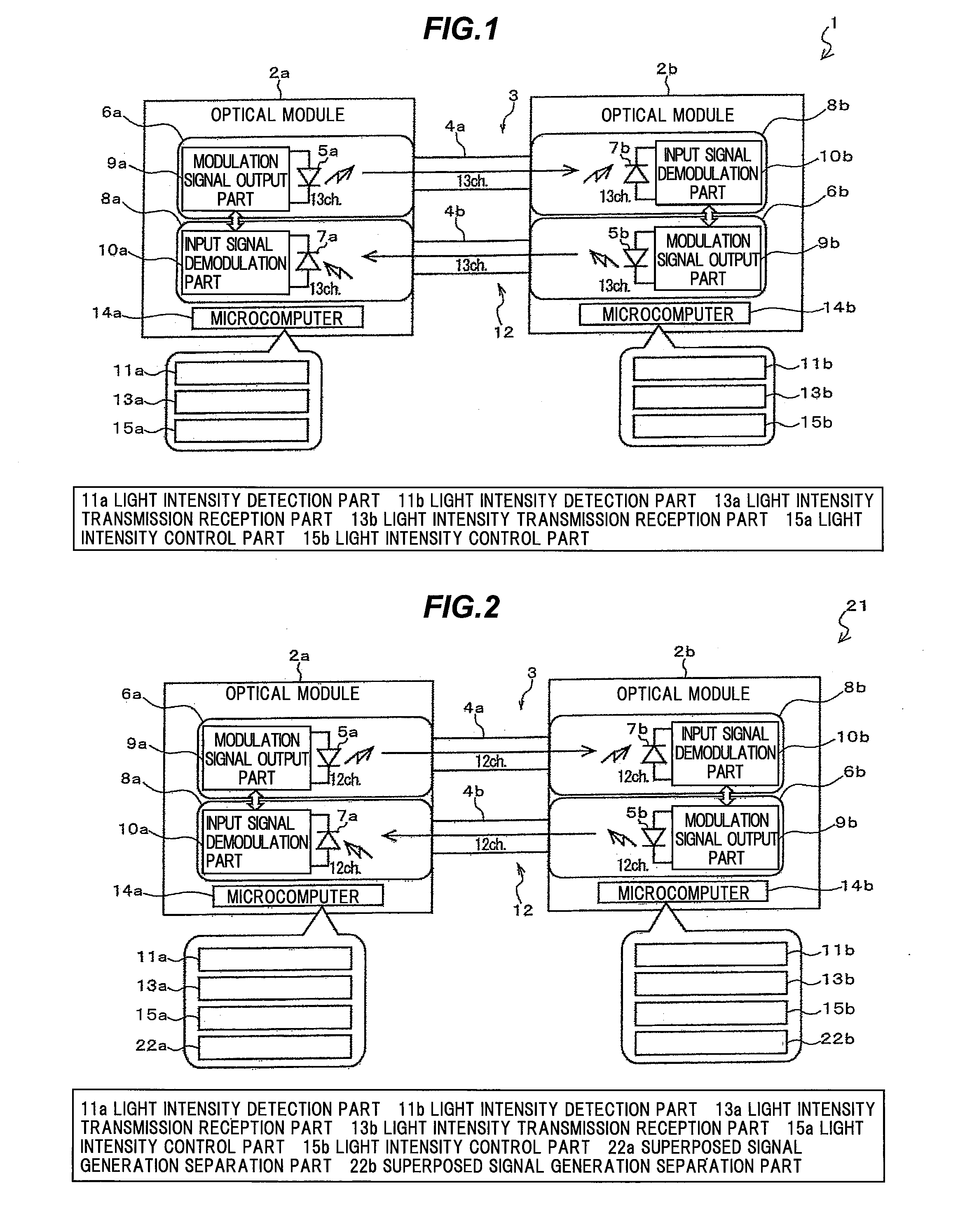
[0035]FIG. 1 is a block diagram schematically showing an optical active cable according to one embodiment of the invention.

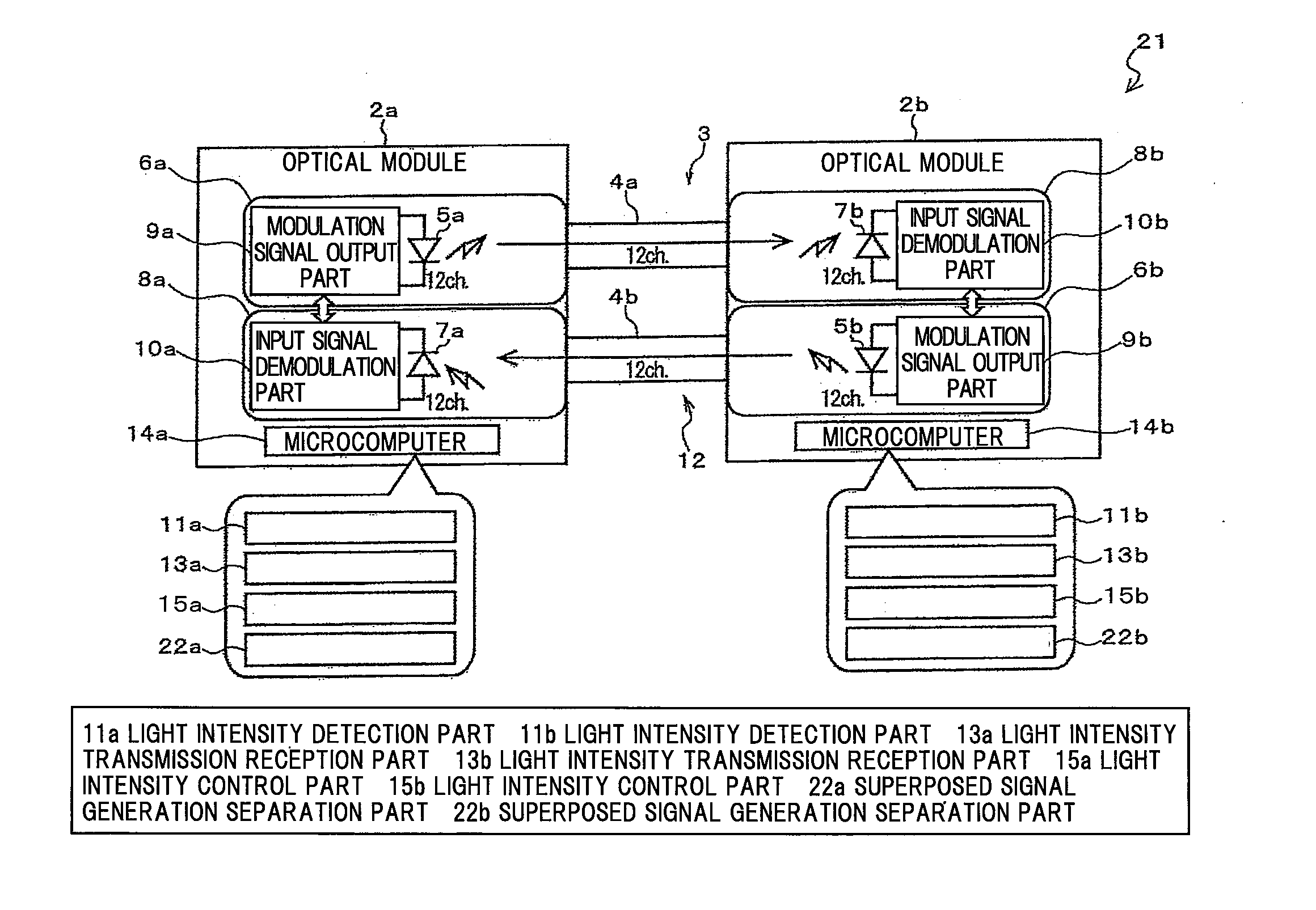
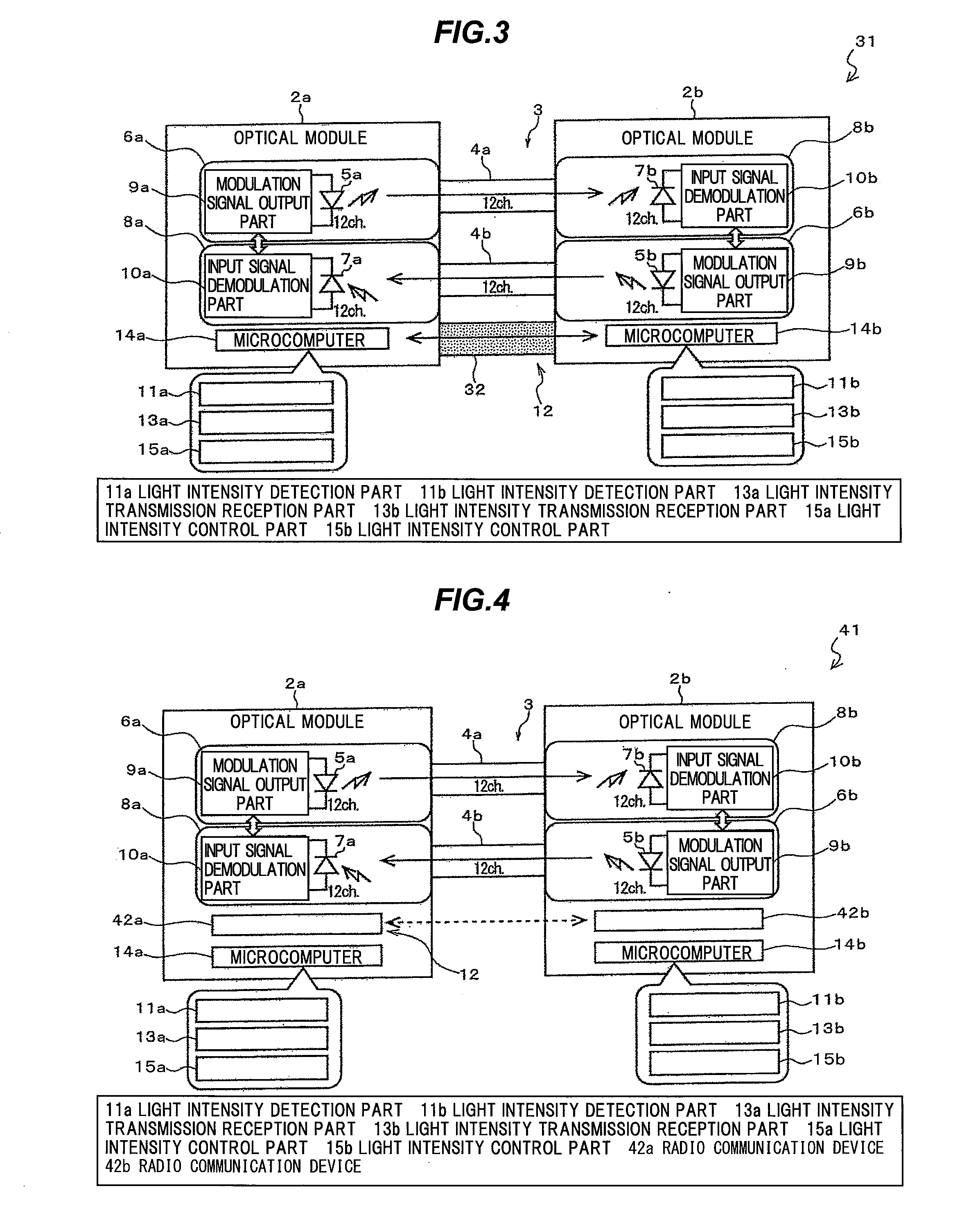
[0036]As shown in FIG. 1, the optical active cable 1 includes an optical cable 3 and an optical module 2a, 2b configured to be disposed in both of end parts of the optical cable 3 respectively.

[0037]The optical module 2a, 2b is configured to include a transmission part 6a, 6b configured to have a light emitting element 5a, 5b and convert an electrical signal to an optical signal and a reception part 8a, 8b configured to have a light receiving element 7a, 7b and convert an optical signal to an electrical signal.

[0038]The optical cable 3 has a transmission side optical fiber 4a and a reception side optical fiber 4b and is configured such that the transmission part 6a of the optical module 2a and the reception part 8b of the optical module 2b...


PUM


Abstract

An optical active cable includes an optical cable, optical modules disposed at both ends of the optical cable and each including a transmission part including a light emitting element and a reception part including a light receiving element, a light intensity detection part disposed in each of the optical modules to detect an intensity of a light received by the light receiving element, a communication means to transmit and receive a data of the light intensity detected by the light intensity detection part between the optical modules, and a light intensity transmission reception part disposed in each of the optical modules to transmit the data of the light intensity detected by the light intensity detection part to an opposite one of the optical modules via the communication means, and to receive the data of the light intensity transmitted from an opposite one of the optical modules via the communication means.

Description

[0001]The present application is based on Japanese patent application No. 2013-132476 filed on Jun. 25, 2013, the entire contents of which are incorporated herein by reference.BACKGROUND OF THE INVENTION[0002]1. Field of the Invention[0003]This invention relates to an optical active cable and an optical transmission system using the optical active cable.[0004]2. Description of the Related Art[0005]An optical active cable is known that includes an optical cable and optical modules disposed at both ends of the optical cable, wherein the optical modules each include a transmission part having a light emitting element and configured to convert an electrical signal to an optical signal and a reception part having a light receiving element and configured to convert an optical signal to an electrical signal.[0006]The light emitting element mounted in the optical module of the optical active cable is e.g. a vertical cavity surface emitting laser (VCSEL). The light receiving element mounted ...

Claims


Application Information

Patent Timeline
Patent Type & Authority Applications(United States)
IPC IPC(8): H04B10/079H04B10/25H04B10/50
CPCH04B10/0795H04B10/2504H04B10/50H04B10/40H04B10/07955
Inventor NIKAIDO, MASAYUKIKATAYAMA, HIROKINAGANUMA, YUKI
Owner HITACHI METALS LTD
Why Eureka
Try Eureka