Head suspension, load beam, and method of manufacturing load beam

a technology of load beam and head suspension, which is applied in the direction of maintaining head carrier alignment, recording information storage, instruments, etc., can solve the problem that and the structure of the related art is complicated

Active Publication Date: 2009-04-09
NHK SPRING CO LTD
View PDF10 Cites 4 Cited by
  • Summary
  • Abstract
  • Description
  • Claims
  • Application Information

AI Technical Summary

Benefits of technology

[0013]An object of the present invention is to provide a technique capable of precisely positioning a slider with respect to a dimple without a complicated structure.
[0015]This aspect forms the concave curved surface of the dimple from the modified part irradiated with a laser beam. The concave curved surface of the dimple, therefore, has low surface roughness and uniform smoothness.
[0017]This aspect surely lowers surface roughness of the concave curved surface of the dimple and makes the concave curved surface uniform.
[0019]This aspect accurately obtains positional data for the concave curved surface of the dimple and accurately positions the slider without a complicated structure.
[0021]According to this aspect, the concave curved surface of the dimple has low surface roughness, and therefore, a slider can precisely be positioned on the dimple without a complicated structure.
[0023]According to this aspect, the head suspension includes the precisely positioned slider, and therefore, can properly control the attitude of the slider.

Problems solved by technology

This positional relationship between the slider and the dimple prevents the precise positioning of the slider onto the dimple because the positions of the slider and dimple are not visually confirmable.
The related art, however, involves a complicated structure.

Method used


Image

  • Head suspension, load beam, and method of manufacturing load beam
  • Head suspension, load beam, and method of manufacturing load beam
  • Head suspension, load beam, and method of manufacturing load beam

Examples


Embodiment Construction

[0035]A head suspension, a load beam, and a method of manufacturing a load beam according to an embodiment of the present invention will be explained in detail with reference to the drawings.

[0036]First, a head suspension having a load beam according to an embodiment of the present invention will be explained. In the following explanation, a “work” implicates any material to be processed, including a semifinished or half-finished product.

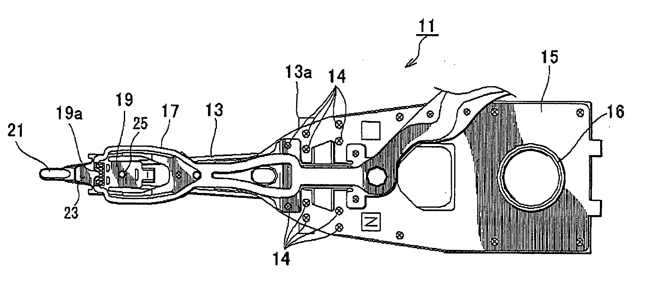
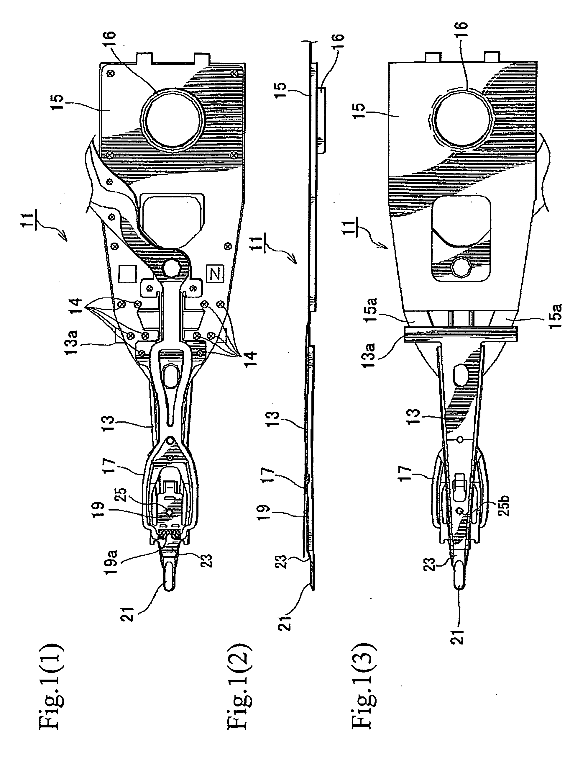
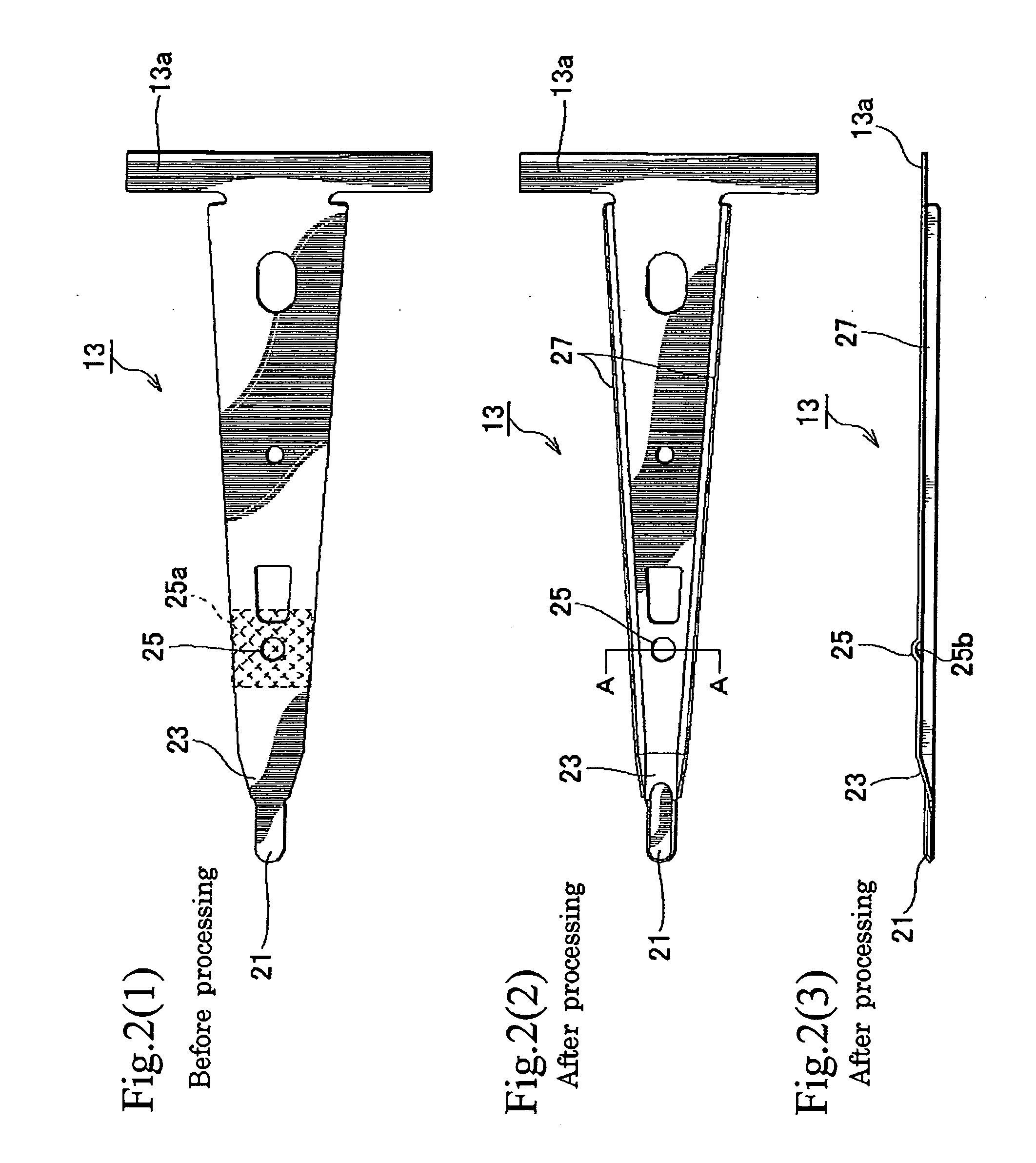
[0037]FIGS. 1(1), 1(2), and 1(3) are plan, side, and back views showing the head suspension according to an embodiment of the present invention.

[0038]The head suspension 11 has a load beam 13, a base plate 15, a flexure 17, and other elements.

[0039]The load beam 13 is produced according to a manufacturing method explained later. The load beam 13 is made of a precision thin plate spring and functions to apply load onto a slider (explained later). Material for the load beam 13 is preferably a metal plate made of austenite-based stainless steel such as...


PUM

PropertyMeasurementUnit
thicknessaaaaaaaaaa
thicknessaaaaaaaaaa
surface roughnessaaaaaaaaaa

Abstract

A method of manufacturing a load beam precisely positions a slider on a dimple of a load beam according to precisely obtained positional data of the dimple, the method includes preparing a work which is a flat plate and serves as the load beam, irradiating at least a part of the work where the dimple is formed with a laser beam, to form a modified part at the irradiated part, carrying out plastic working on the modified part, to form the dimple having a concave curved surface at the modified part, taking an image of the concave curved surface of the dimple, obtaining the positional data of the dimple from the image, and positioning the slider on the dimple according to the positional data.

Description

BACKGROUND OF THE INVENTION[0001]1. Field of the Invention[0002]The present invention relates to a head suspension for supporting a slider in a disk drive such as an external storage device of a computer, a load beam which is a part of the head suspension, and a method of manufacturing the load beam.[0003]2. Description of Related Art[0004]Disk drives such as magnetic disk drives and optical disk drives are widely used as external storage devices of computers. Among the disk drives, a magnetic disk drive or a hard disk drive (HDD) has a head suspension for supporting a magnetic head slider (hereinafter simply referred to as “slider”).[0005]The head suspension includes a base plate, a load beam, a flexure attached to the load beam, and the like. The load beam supports a gimbal which is a plate spring. A front end of the gimbal forms a tongue serving as a slider mount. To the tongue, the slider is attached with, for example, an adhesive. The slider is slightly pushed with spring force...

Claims


Application Information

Patent Timeline
Patent Type & Authority Applications(United States)
IPC IPC(8): G11B5/48G11B5/127
CPCG11B5/4826Y10T29/49032G11B5/4833
Inventor NOJIMA, AKIRAHORIUCHI, TAKASHI
Owner NHK SPRING CO LTD
Why Eureka
Try Eureka