Shock absorber

a technology of shock absorber and shock absorber, which is applied in the direction of shock absorber, spring/damper, axle suspension, etc., can solve problems such as complex structure, and achieve the effect of more reliably lubricating a sliding surfa

Active Publication Date: 2015-05-26
KYB CORP
View PDF9 Cites 3 Cited by
  • Summary
  • Abstract
  • Description
  • Claims
  • Application Information

AI Technical Summary

Benefits of technology

[0014]The present invention aims to provide a shock absorber capable of more reliably lubricating a sliding surface of an upper bearing without complicating a structure.

Problems solved by technology

In the conventional front fork, the rod guide needs to be provided with the damping valve in addition to the check valve to reliably lubricate the sliding surface of the upper bearing, which leads to a complicated structure.

Method used


Image

  • Shock absorber
  • Shock absorber
  • Shock absorber

Examples


first embodiment

[0022]A first embodiment is described.

[0023]A shock absorber according to this embodiment is applied to a front fork interposed between a vehicle body and a front wheel of a two-wheeled vehicle and adapted to damp road vibration input to the front wheel.

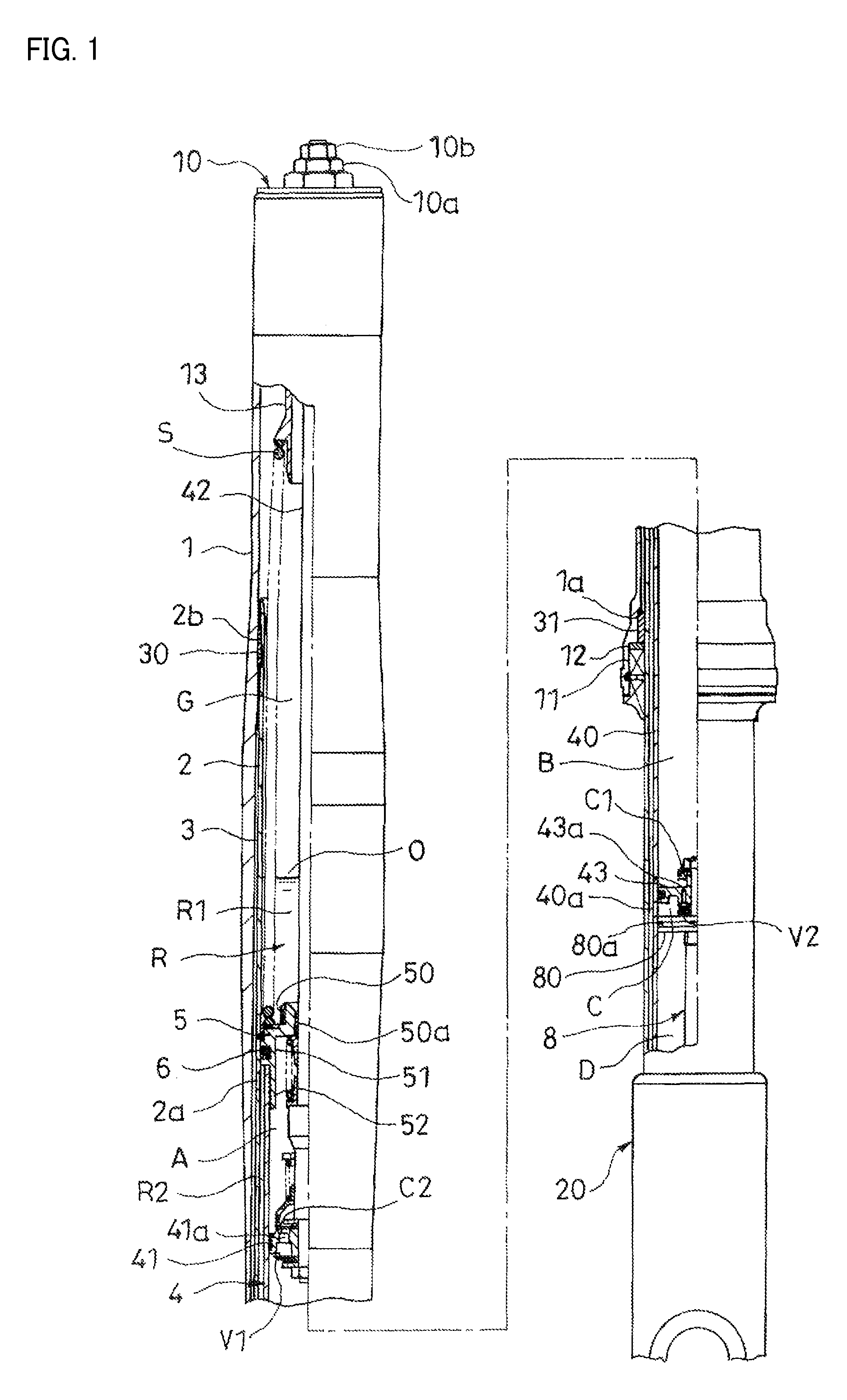
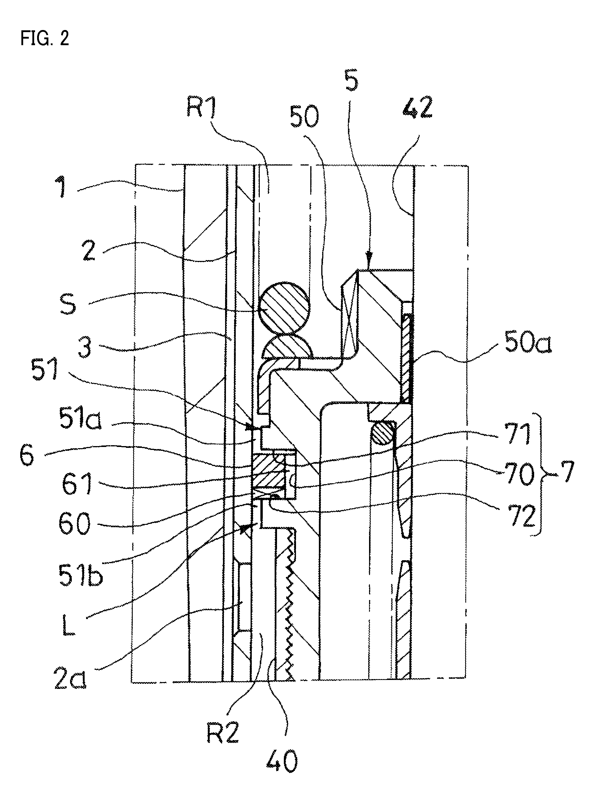
[0024]As shown in FIG. 1, the front fork includes a shock absorber main body composed of a vehicle-body side tube 1 and a wheel side tube 2 to be slidably inserted into the vehicle-body side tube 1 via a pair of upper and lower bearings 30, 31. The upper bearing 30 is mounted on the outer periphery of the wheel side tube 2 and the lower bearing 31 is mounted on the inner periphery of the vehicle-body side tube 1, and a lubrication clearance 3 is formed between these bearings 30, 31.

[0025]The front fork includes a damper 4 including a cylinder 40, a piston 41 and a rod 42. The cylinder 40 stands in an axial center part of the wheel side tube 2 and stores a working fluid. The piston 41 is held in sliding contact with the inner peripher...

second embodiment

[0068]Next, a second embodiment is described.

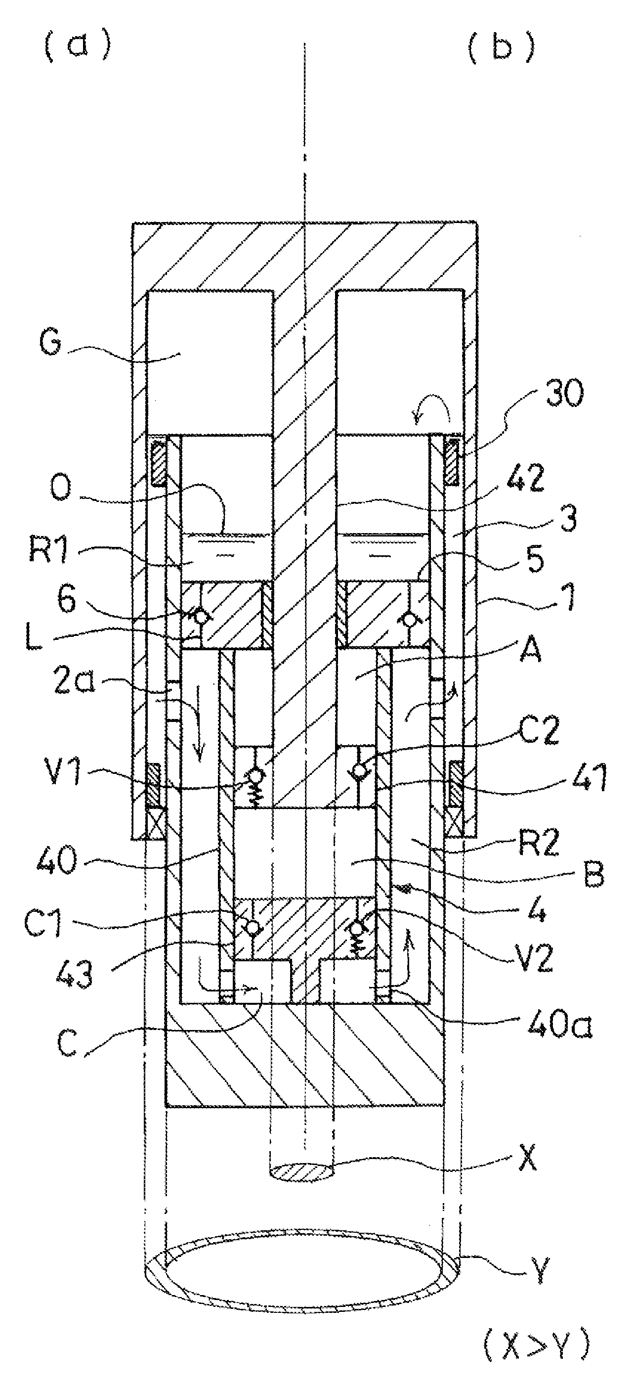
[0069]A shock absorber according to this embodiment is applied to a front fork as in the first embodiment. A basic configuration of the front fork is the same as in the first embodiment, but differs in that the cross-sectional area Y of the lubrication clearance 3 is larger than the cross-sectional area X of the rod 42 as shown in FIG. 4.

[0070]Reference is made to the first embodiment for the explanation of the detailed configuration of the front fork. The operation of the front fork and effects brought about by configuration differences in this embodiment are described below.

[0071]When the front fork is extended, the extension side working chamber A is pressurized and the working fluid in the extension side working chamber A opens the extension side damping valve V1 of the piston 41 and moves to the compression side working chamber B as in the first embodiment, whereby the working fluid that becomes insufficient by as much as the volume ...


PUM


Abstract

A shock absorber includes a shock absorber main body composed of a vehicle-body side tube and a wheel side tube and formed with a lubrication clearance, a damper including a cylinder, a piston which partitions the interior of the cylinder into two working chambers, and a rod, a reservoir chamber composed of an air chamber and a working fluid chamber, a partition wall member for partitioning the working fluid chamber into an upper working fluid chamber and a lower working fluid chamber, a flow path having a check valve for permitting only a movement of the working fluid from the upper working fluid chamber to the lower working fluid chamber, and a communication path for allowing communication between the lower working fluid chamber and the lubrication clearance. A cross-sectional area of the lubrication clearance and that of the rod are different.

Description

TECHNICAL FIELD[0001]This invention relates to a shock absorber.BACKGROUND ART[0002]JP1992-312221A discloses a shock absorber interposed between a vehicle body and a wheel to damp road vibration input to the wheel. This shock absorber is applied to a front fork for suspending a front wheel of a two-wheeled vehicle and includes a shock absorber main body composed of a vehicle-body side tube and a wheel side tube to be slidably inserted into the vehicle-body side tube via a pair of upper and lower bearings as shown in FIG. 1 of the above document.[0003]The upper bearing is mounted on the outer periphery of the wheel side tube and the lower bearing is mounted on the inner periphery of the vehicle-body side tube, and a working fluid stored in a lubrication clearance formed between these bearings functions as a lubricant to provide good slidability.[0004]An upright damper including a cylinder which stands in an axial center part of the wheel side tube and in which the working fluid is fi...

Claims


Application Information

Patent Timeline
Patent Type & Authority Patents(United States)
IPC IPC(8): F16F9/18B62K25/04B62K25/08
CPCF16F9/18B62K25/08B62K2025/048F16F9/064F16F9/368F16F9/06
Inventor SUMIDA, MASASHI
Owner KYB CORP
Why Eureka
Try Eureka