Ultrahigh speed image pickup device

Inactive Publication Date: 2006-04-18
ETOH TAKEHARU +1
View PDF5 Cites 6 Cited by
  • Summary
  • Abstract
  • Description
  • Claims
  • Application Information

AI Technical Summary

Benefits of technology

[0044]In this case, since the intercepting film is used as a drain voltage control conductive film, introduction of a new conductive film can be avoided. Specifically, since the intercepting film has an extremely large area and a large electric capacity, it is difficult to apply to this voltages that suddenly change for electronic shuttering. Moreover, since the intercepting film covers substantially the entire area of the image capturing area, the image quality could be affected if voltages that suddenly change would be applied every step of transfer during image capturing. For this reason, the intercepting film is normally not used as a power transmission film. However, the drain for serial overwriting is always activated during image capturing and deactivated for read-out after image capturing is finished. The activation and deacti

Problems solved by technology

The biggest problem of the image sensor of FIG. 22 is a low aperture efficiency.
However, this constructio

Method used


Image

  • Ultrahigh speed image pickup device
  • Ultrahigh speed image pickup device
  • Ultrahigh speed image pickup device

Examples


first embodiment

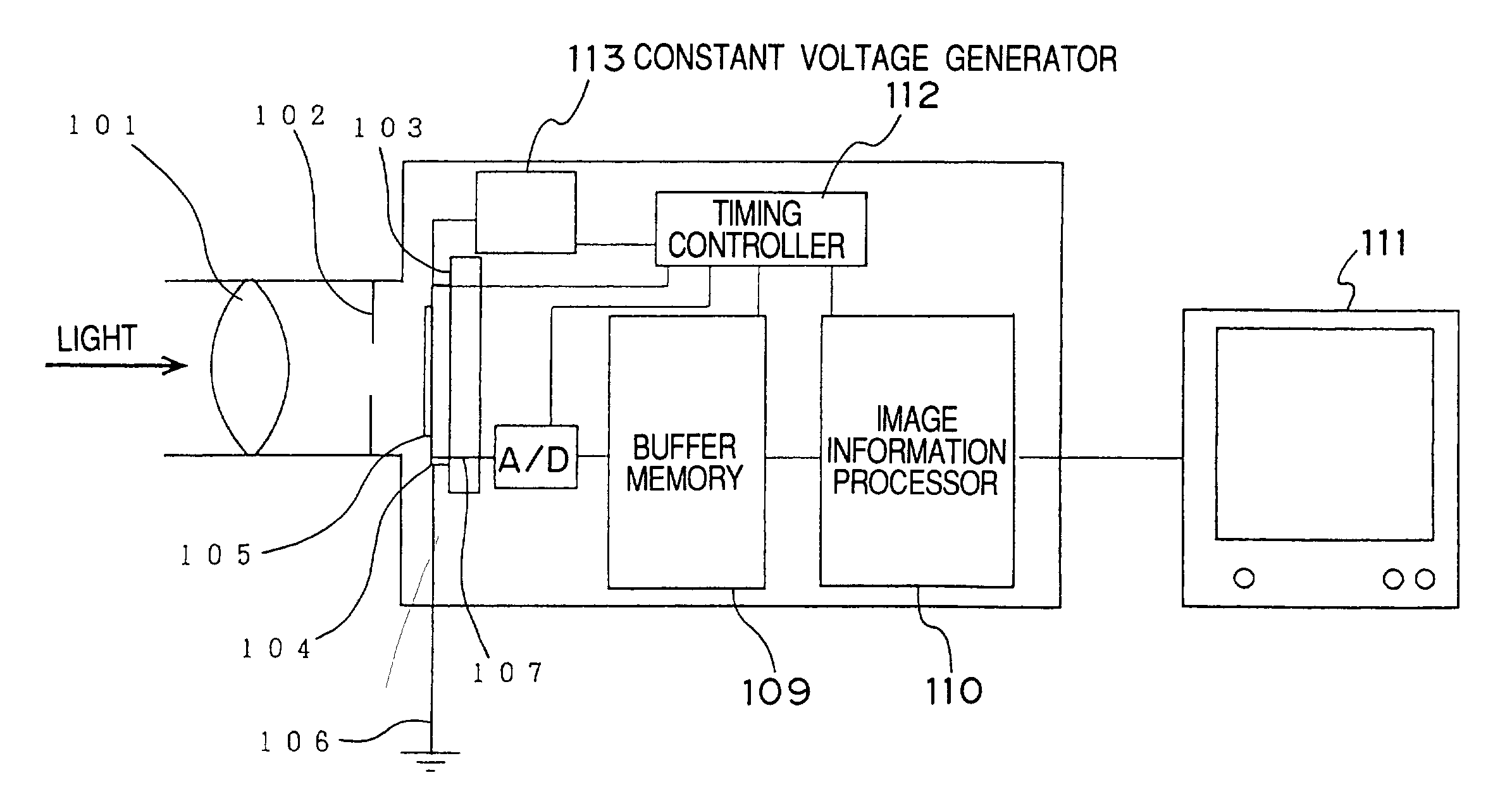
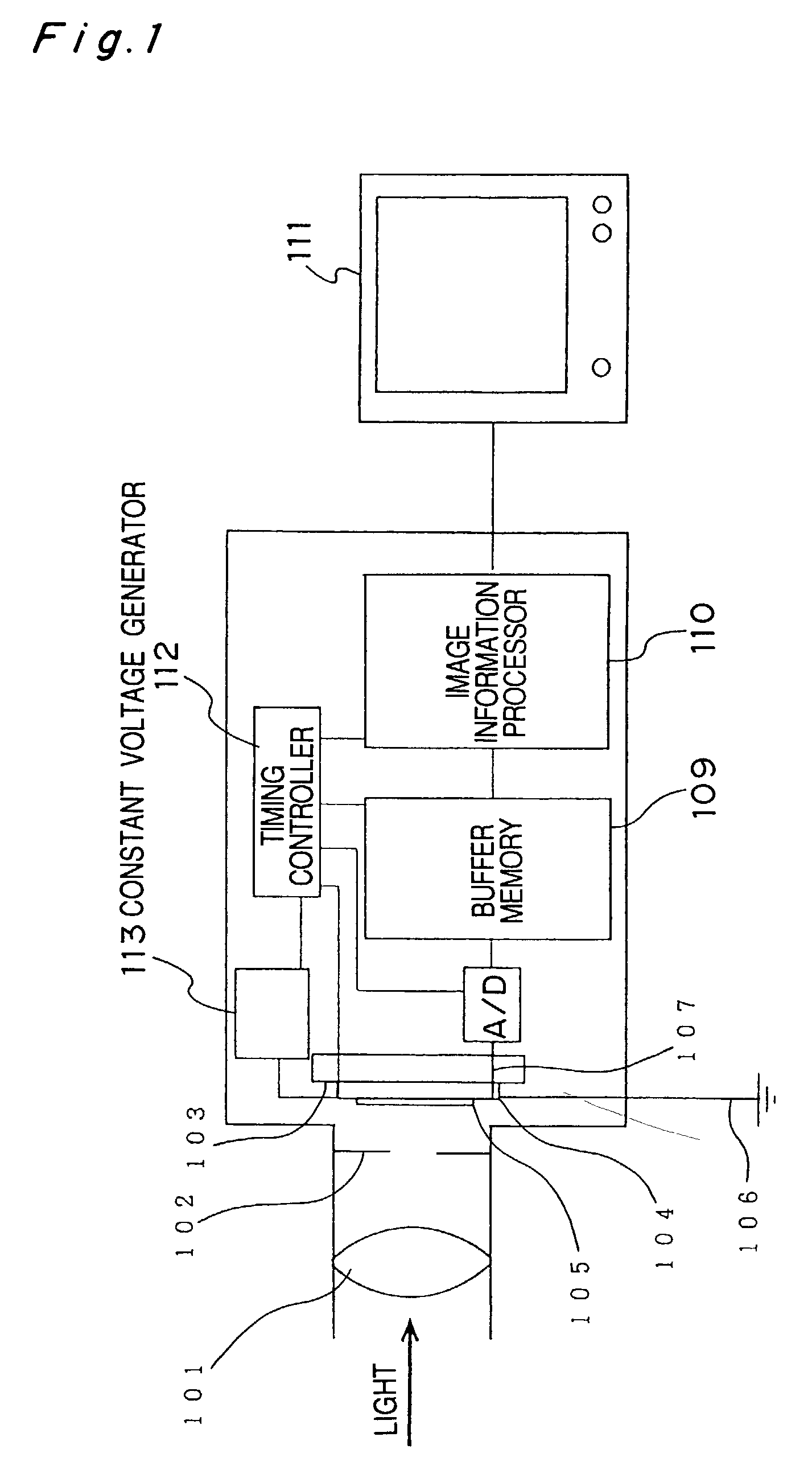
[0069]FIG. 1 shows the structure of the entire image capturing apparatus. Light incident on a lens 101 passes through an external shutter 102 and form an image on an image capturing area 105 on a chip 104 of an image sensor 103 for ultrahigh-speed image capturing. Charges are generated in accordance with the intensity of the incident light during image capturing, and excessive charges generated by excessive incident light are discharged to ground through a drain wire 106. Afterimage capturing, the image information (in this case, charge) stored in the image sensor through a read-out line 107 is converted to digital information by an AD converter 108, and then stored in a buffer memory 109. Then, the image information is converted to image information of each of the continuous frames by an image information processor 110, and then output to the outside of the image capturing apparatus. This image information can be viewed as a visible image through a monitor 11.

[0070]The image captur...

second embodiment

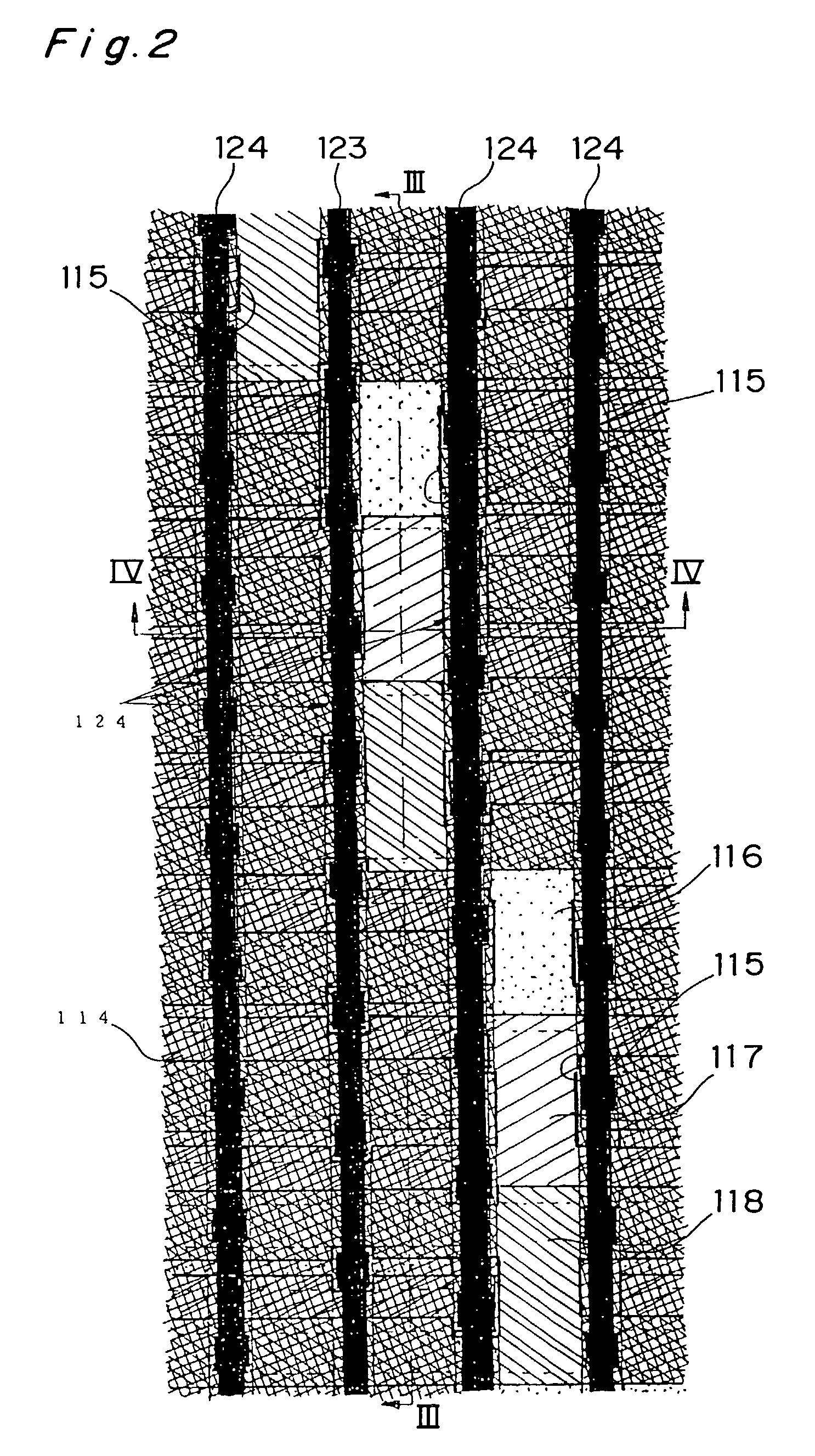
[0080]In the image sensor for ultrahigh-speed image capturing of a second embodiment of the present invention shown in FIGS. 11 and 12, the size of the charge transfer paths 123 in a direction perpendicular to the charge transfer direction is increased at the windows 115. In correspondence therewith, a gently curved portion 123c is provided on each charge transfer path 123. Further, a drain 128 for serial overwriting is provided on a right side of the charge transfer path 123 immediately above each window 115.

[0081]Moreover, the windows 115 are each fringed with a tungsten layer 132 situated one layer below the aluminum intercepting film 114. This construction is reducing a smearing phenomenon caused by light or photoelectrons entering peripheral charge transfer paths 123 from the windows 115.

[0082]In the image sensor of the present embodiment, since the aperture efficiency is high compared to the first embodiment, the sensitivity to light is dramatically improved. Additionally, sin...

third embodiment

[0093]FIG. 13 shows a third embodiment of the present invention. In the third embodiment, portions 136, 137 and 138 of the charge transfer electrode corresponding to the window 115 are not perpendicular but slanted to the charge transfer direction so as to be wedged-shaped. Therefore, the length of the sides of the portions 136, 137 and 138 where an electronic field fringe is caused, that is, the length of overlapping portions 139 and 140 of the electrodes situated at upper and lower portions thereof (on the upstream and the downstream sides in the charge transfer direction) them are extremely long. Consequently, the ratio of the area of a region 141 where the field fringe effect is caused shown by the oblique lines in the figure with respect to the area of the window 115 is high.

[0094]FIG. 14 shows the potential 150 and the charge transfer direction 151 in the present embodiment. As is apparent from FIG. 14, in the present embodiment, the portion of the charge transfer path within ...


PUM


Abstract

An ultra-high speed image sensor is a frame transfer type. A charge corresponding to an intensity of a incident ray is generated at an element of a charge transfer path corresponding to each window. The generated charge is transferred on the charge transfer path by voltages applied from the charge transfer electrodes to. Each of the charge transfer electrodes to has a larger size in a charge transfer direction at portions corresponding to the window than that at portions covered with the intercepting film.

Description

[0001]This application is the national phase under 35 U.S.C. § 371 of PCT International Application No. PCT / JP00 / 06700 which has an International filing date of Sep. 28, 2000, which designated the United States of America.TECHNICAL FIELD[0002]The present invention relates to an image sensor for ultrahigh-speed image capturing suitable for continuous image capturing of high-speed motions such as breakage and explosion of materials and high-speed flows.BACKGROUND ART[0003]The speed of image capturing by normal solid-state image sensors is limited by the information transfer capability of a read-out line for reading out image information from the image sensor to the outside of the image sensor. Precisely, the image capturing speed is limited by the information processing capabilities of an output circuit that performs processing preceding the image information read-out and an AD converter that performs processing succeeding the image information read-out, that is, a sampling rate. A st...

Claims


Application Information

Patent Timeline
IPC IPC(8): G06K7/00H01L21/339H01L27/148H01L29/762H01L31/10H04N5/335H04N5/359H04N5/369H04N5/3725
CPCH01L27/14806
Inventor ETOH, TAKEHARU
Owner ETOH TAKEHARU
Why Eureka
Try Eureka