
Disparity value deriving device, equipment control system, movable apparatus, robot, and disparity value deriving method

a technology of disparity value and deriving device, which is applied in the field of disparity value deriving device, an equipment control system, a movable apparatus, a robot, etc., can solve the problems of high memory consumption, difficult to extract image features in a portion, and involving a heavy image processing load

Inactive Publication Date: 2015-10-15
RICOH KK
View PDF12 Cites 10 Cited by
  • Summary
  • Abstract
  • Description
  • Claims
  • Application Information

AI Technical Summary

Benefits of technology

The present invention provides a device and method for deriving a disparity value for an object by comparing images obtained from different positions. The device includes a reducer for generating a reduced image, a calculator for calculating the degree of matching of regions in the image, a synthesizer for obtaining a synthesis degree of matching, a deriving unit for deriving the disparity value based on the matching degrees, a generator for generating a first disparity image, and an enlarging unit for enlarging the first disparity image by a second ratio to generate a second disparity image. The technical effect of the invention is to provide a more accurate and reliable method for deriving the disparity value for object recognition.

Problems solved by technology

However, it is difficult to extract image features in a portion where texture in an image is weak, and the block matching method may not provide accurate disparity.
However, the technique disclosed in Japanese Patent Application Laid-open No. 2012-181142 derives disparity values for the entire image obtained by a stereo camera, disadvantageously requiring high memory consumption and involving a heavy image processing load.

Method used


Image

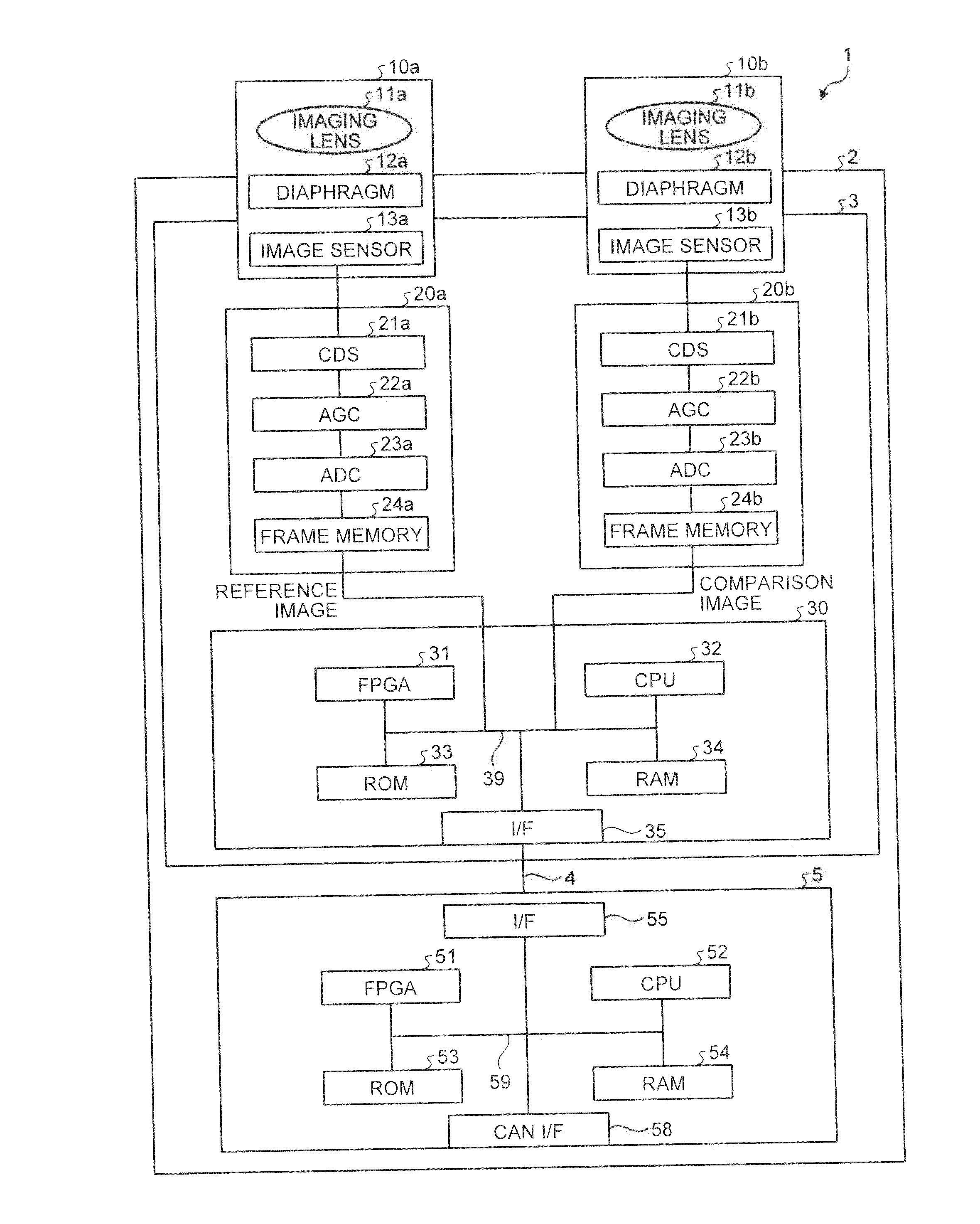
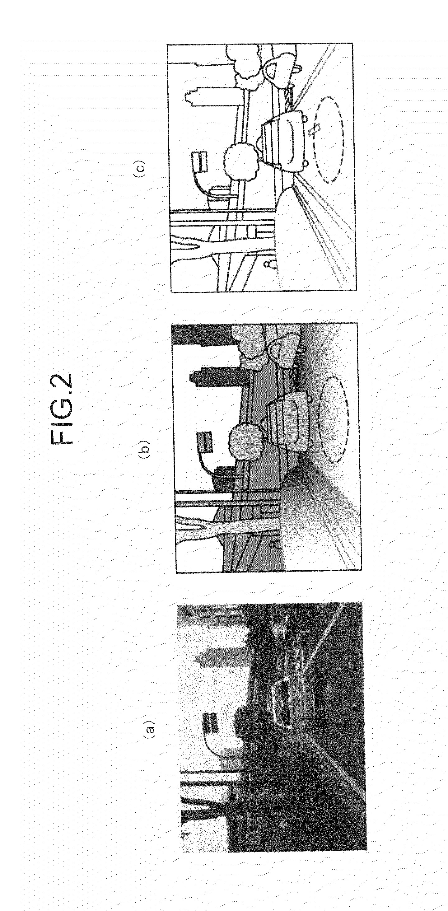
  • Disparity value deriving device, equipment control system, movable apparatus, robot, and disparity value deriving method
  • Disparity value deriving device, equipment control system, movable apparatus, robot, and disparity value deriving method
  • Disparity value deriving device, equipment control system, movable apparatus, robot, and disparity value deriving method

Examples


Embodiment Construction

[0030]Embodiments of the present invention will be described below with reference to the accompanying drawings.

[0031]Overview of Distance Measurement Method Using SGM Method

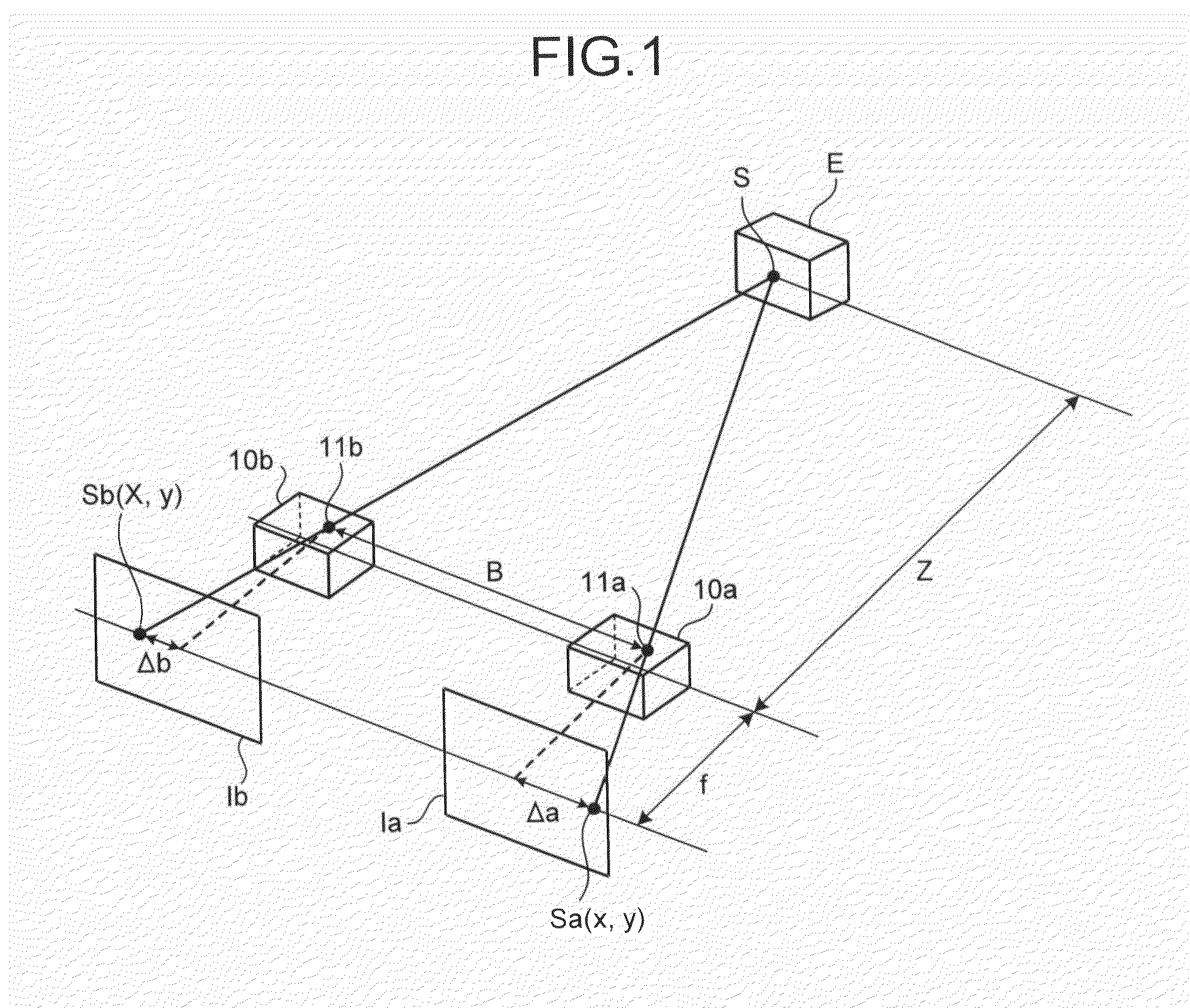
[0032]Referring first to FIG. 1 to FIG. 6, an overview of a distance measurement method using the semi-global matching (SGM) method will be described. The SGM method is disclosed in Accurate and Efficient Stereo Processing by Semi-Global Matching and Mutual Information) and a brief explanation is given below.

[0033]Principle of Distance Measurement

[0034]Referring to FIG. 1, the principle of measuring the distance from a stereo camera to an object will be described, in which disparity of the object is derived as a disparity value by conducting stereo imaging using the stereo camera, and the disparity value is used to measure the distance from the stereo camera to the object. FIG. 1 is an illustration of the principle of deriving the distance from imaging devices to an object. The following description explains proc...


PUM


Abstract

An image reducer executes a reduction process on a comparison image to generate a reduced comparison image, and executes a reduction process on a reference image to generate a reduced reference image. A disparity value deriver (a deriving unit) derives a disparity value by setting the minimum value of synthesized costs of pixels in the reduced comparison image in connection with a reference pixel in the reduced reference image, which have been calculated by a cost synthesizer. A disparity image generator generates a reduced disparity image, which is an image obtained by replacing the luminance values of the respective pixels in the reduced reference image with the disparity values corresponding to the pixels. The disparity image enlarger executes an enlargement process for enlarging the image size of the reduced disparity image generated by the disparity image generator to generate a disparity image.

Description

CROSS-REFERENCE TO RELATED APPLICATIONS[0001]The present application claims priority to and incorporates by reference the entire contents of Japanese Patent Application No. 2014-082182 filed in Japan on Apr. 11, 2014 and Japanese Patent Application No. 2015-055439 filed in Japan on Mar. 18, 2015.BACKGROUND OF THE INVENTION[0002]1. Field of the Invention[0003]The present invention relates to a disparity value deriving device, an equipment control system, a movable apparatus, a robot, and a disparity value deriving method.[0004]2. Description of the Related Art[0005]In recent years, vehicle-mounted systems have generally been used for preventing automobile collisions by measuring the distance between automobiles or the distance between an automobile and an obstacle. Methods of measuring the distance include a method based on a stereo matching process using the principle of triangulation using a stereo camera having two cameras.[0006]The stereo matching process is a process of obtainin...

Claims


Application Information

Patent Timeline
Patent Type & Authority Applications(United States)
IPC IPC(8): H04N13/02G06K9/46B60R1/00H04N5/265G06K9/62G06T7/00H04N13/239
CPCH04N13/0296G06K9/6202G06T7/004G06K2009/4666H04N5/265G06K9/46B60R1/00B60R2300/107H04N2013/0081G06T2207/20016G06T2207/30252G06T7/593H04N13/239H04N13/296G06V20/58G06V10/751G06V2201/12
Inventor ZHONG, WEISAITO, KIICHIRO
Owner RICOH KK
Learn More