Combustion chamber arrangement

a combustion chamber and arrangement technology, applied in mechanical equipment, machines/engines, lighting and heating apparatus, etc., can solve the problems of not being able to provide a flow of coolant over the lip, not being able to expose the discharge nozzle to the hot gases in the combustion chamber, and being heavy and expensive to manufactur

Active Publication Date: 2015-10-22
ROLLS ROYCE PLC
View PDF6 Cites 13 Cited by
  • Summary
  • Abstract
  • Description
  • Claims
  • Application Information

AI Technical Summary

Benefits of technology

[0009]Therefore the present invention seeks to provide a novel combustion chamber arrangement which reduces or overcomes the above mentioned problem.

Problems solved by technology

This arrangement has several problems.
The cooling ring is manufactured from a machined forging, is heavy and is expensive to manufacture.
The lip which extends from the cooling ring to direct the coolant from the apertures in the cooling ring over the surface of the discharge nozzle extends beyond the downstream ends of the tiles and hence may be exposed to the hot gases in the combustion chamber and may fail exposing the discharge nozzle to the hot gases in the combustion chamber.
The segments, or tiles, with apertures extending there-through to provide film cooling of the inner surfaces of the segments, or tiles, are provided with peripheral walls to form a sealed cavity and these segments, or tiles, are not able to provide a flow of coolant over the lip of the cooling ring without compromising the efficiency of cooling of the segments, or tiles.

Method used


Image

  • Combustion chamber arrangement
  • Combustion chamber arrangement
  • Combustion chamber arrangement

Examples


Embodiment Construction

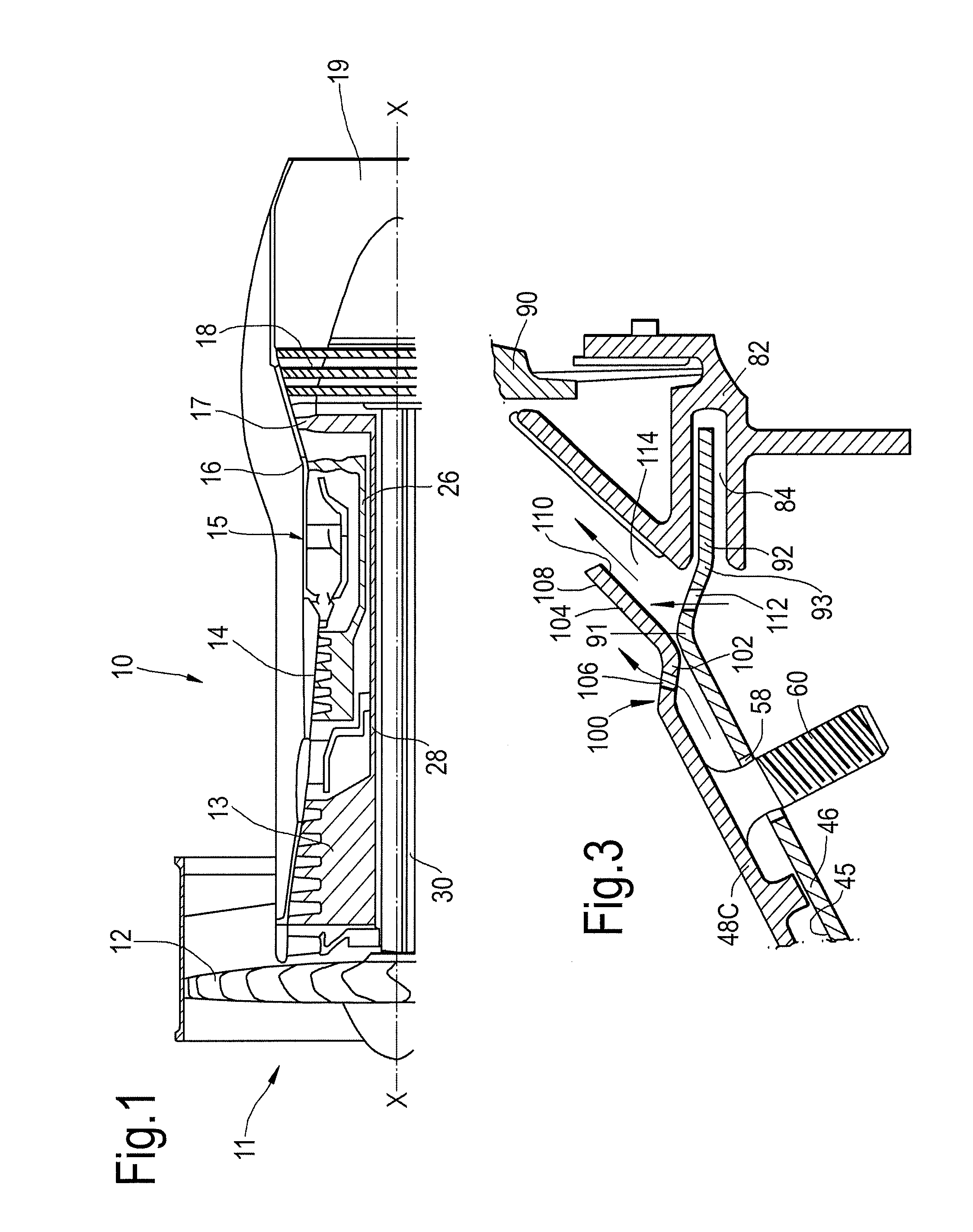
[0036]A turbofan gas turbine engine 10, as shown in FIG. 1, comprises in flow series an intake 11, a fan 12, an intermediate pressure compressor 13, a high pressure compressor 14, a combustion chamber 15, a high pressure turbine 16, an intermediate pressure turbine 17, a low pressure turbine 18 and an exhaust 19. The high pressure turbine 16 is arranged to drive the high pressure compressor 14 via a first shaft 26. The intermediate pressure turbine 17 is arranged to drive the intermediate pressure compressor 13 via a second shaft 28 and the low pressure turbine 18 is arranged to drive the fan 12 via a third shaft 30. In operation air flows into the intake 11 and is compressed by the fan 12. A first portion of the air flows through, and is compressed by, the intermediate pressure compressor 13 and the high pressure compressor 14 and is supplied to the combustion chamber 15. Fuel is injected into the combustion chamber 15 and is burnt in the air to produce hot exhaust gases which flow...


PUM


Abstract

A combustion chamber arrangement including an outer wall and an inner wall spaced from the outer wall and the outer wall supports the inner wall. The inner wall including at least one row of circumferentially arranged tiles. At least one tile in the at least one row of tiles having an L, or V, shaped downstream end and the downstream end of the tile in the row of tiles having a first portion extending from the downstream end of the tile towards and sealing with an inner surface of the outer wall and a second portion extending from the first portion in a downstream direction and away from the inner surface of the outer wall. The first portion of the downstream end of the tile having a plurality of apertures to supply coolant over an inner surface of the second portion of the downstream end of the tile.

Description

FIELD OF THE INVENTION[0001]The present invention relates to a combustion chamber arrangement and in particular to a gas turbine engine combustion chamber arrangement.BACKGROUND TO THE INVENTION[0002]Gas turbine engine combustion chambers experience extremely high temperatures in operation and the walls of the combustion chambers are generally cooled using a coolant.[0003]It is known to provide combustion chambers comprising an inner wall and an outer wall or combustion chamber comprising segments, or tiles, and in particular the inner wall comprises a plurality of segments, or tiles, supported on the outer wall. The tiles consist of high temperature resistant material, e.g. a nickel base superalloy. The tiles are spaced from the inner surface of the outer wall to provide a passage for coolant. The outer wall of the combustion chamber may have apertures extending there-through to provide impingement cooling of the outer surfaces of the tiles. The tiles may have pedestals projecting ...

Claims


Application Information

Patent Timeline
Patent Type & Authority Applications(United States)
IPC IPC(8): F23R3/00F02C7/18
CPCF23R3/005F02C7/18F23R3/002F23R3/007F23R2900/03042F23R2900/03044
Inventor JOPP, LISA JANEWILLIS, NATHAN THOMAS
Owner ROLLS ROYCE PLC
Why Eureka
Try Eureka