Wind turbine blade with transition region

a technology of transition region and wind turbine blade, which is applied in the direction of reaction engine, machine/engine, mechanical apparatus, etc., can solve the problems of increasing the weight of the blade and complicating the layup procedur

Active Publication Date: 2014-06-05
LM WP PATENT HLDG
View PDF9 Cites 13 Cited by
  • Summary
  • Abstract
  • Description
  • Claims
  • Application Information

AI Technical Summary

Benefits of technology

[0010]The object of the invention is obtained in that the transition region additionally comprises a third type of reinforcement fibre material differing from both the first and the second reinforcement fibre material and having an E-modulus between that of the first reinforcement fibre material and that of the second reinforcement fibre material. The first reinforcement fibre material is fibreglass. Typically, glass fibres have an E-modulus of about 70 GPa and a density of about 2.54 g / cm3. The second reinforcement fibre material is carbon fibre. Today, carbon fibre is a preferred material for the reinforcement fibre material, as this type of fibres is used increasingly due to its low weight and high stiffness. Carbon fibres typically have a density of about 1.75 g / cm3 and an E-modulus of about 230-600 GPa or more depending on the type of carbon fibre. Although WO 2003 / 078832 (also by the same applicant) solves the problem of the stiffness jump between carbon fibres and fibreglass, it has been found that it is necessary to have a local thickening of the blade structure in order to accommodate for a smooth transition in the stiffness of the blade. However, such thickening increases the weight of the blade and also complicates the layup procedure when moulding the blades.
[0011]The present invention alleviates this problem by means of providing the third type of reinforcement fibre material having an E-modulus between that of fibreglass and carbon fibres. Thereby, it is possible to provide a very smooth transition between the first and the second reinforcement fibre material and thereby substantially reduce or eliminate the stress concentration in the transition region between the first region comprising predominantly fibreglass and the second region comprising predominantly carbon fibres. Thus, the reduction or elimination of stress concentrations allows for a reduction in thickness and thereby of the amount of material used.
[0016]According to an additional embodiment the third reinforcement fibre material is made of metal fibres, preferably steel fibres. Steel fibres are preferred due to their relative low costs and their E-modulus being between that of glass fibres and that of carbon fibres. Steel fibres typically have an E-modulus of about 200 GPa and a density of about 7.85 g / cm3. Further, metal fibres and in particular steel fibres, have excellent compatibility with carbon fibres and fibreglass, thus lowering the possibility of e.g. delamination.
[0025]According to a further embodiment the fibres or bundles of fibres of the first type of reinforcement fibres extend with differing lengths from the first region and into the transition region, fibres or bundles of fibres of the second type of reinforcement fibres extend with differing lengths from the second region and into the transition region and fibres or bundles of fibres of the third type of reinforcement fibres extend in the transition region between the first and the second type of fibres extending from the first and the second region, respectively. As a result, it is possible to provide an extremely smooth transition between the first and the second type of reinforcement fibres so that stress concentrations are eliminated or reduced substantially between the first region comprising predominantly the first type of reinforcement fibres and the second region comprising predominantly the second type of reinforcement fibres.
[0028]According to a further embodiment the fibres of the first region, the second region and the transition region extend predominantly in the longitudinal direction of the blade. As a result, the fibres are oriented so as to optimally withstand the loads to which the blade is subjected during use, i.e. especially bending moments, and typically to provide stiffness against flapwise deflections of the blade.

Problems solved by technology

However, such thickening increases the weight of the blade and also complicates the layup procedure when moulding the blades.

Method used


Image

  • Wind turbine blade with transition region
  • Wind turbine blade with transition region
  • Wind turbine blade with transition region

Examples


first embodiment

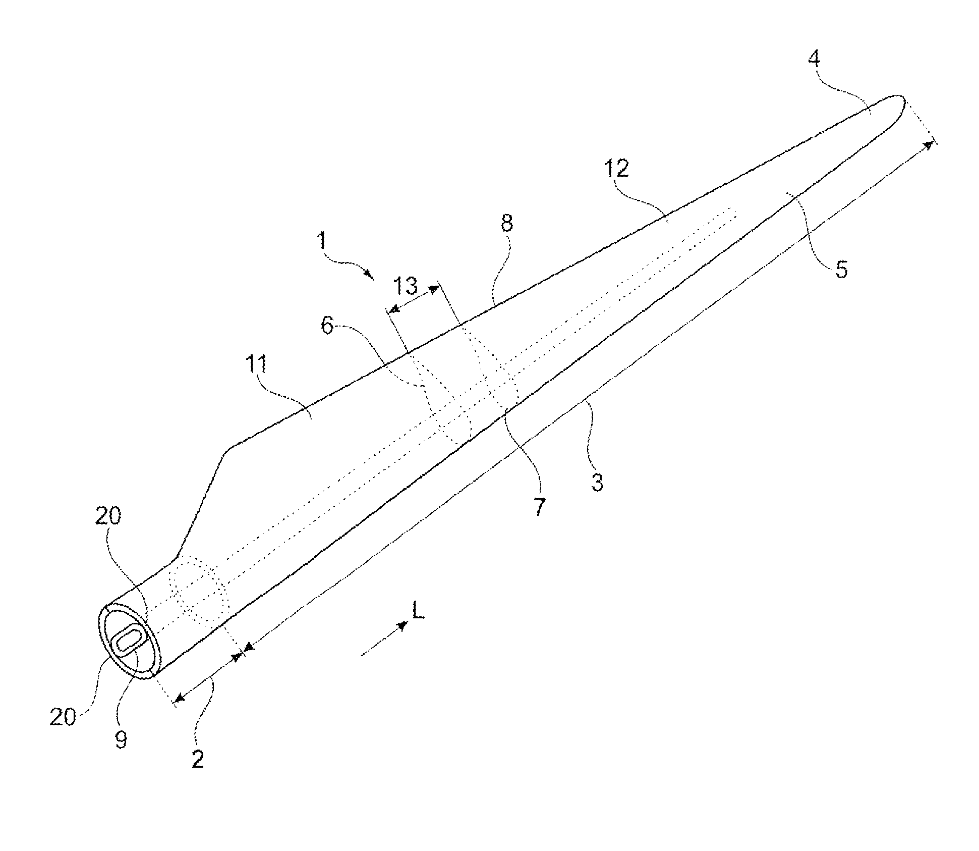
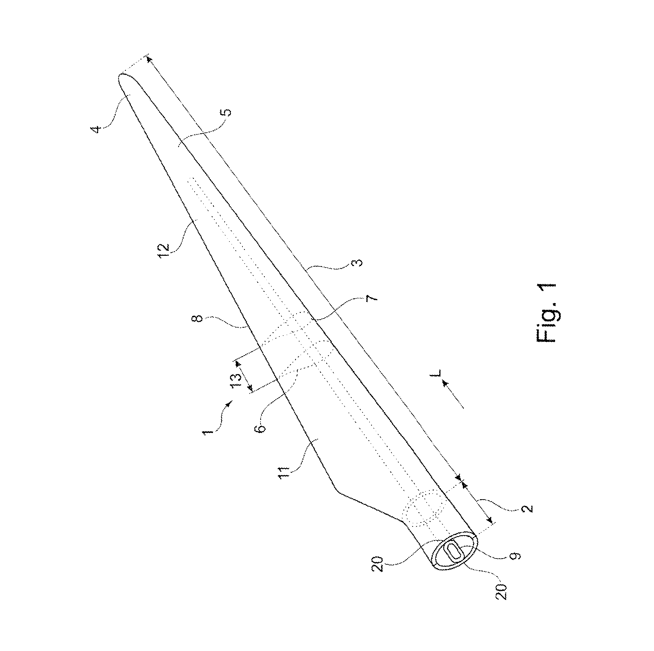
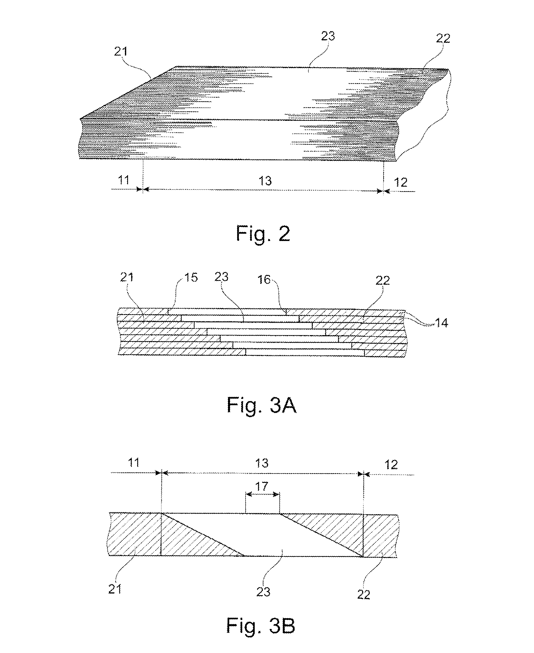
[0047]the invention shown in FIG. 2 is a sectional view of a wind turbine blade shell at the transition region. The first region 11 of the blade 1 is reinforced predominantly with the first reinforcement fibre material 21 if form of glass fibres, the first region 11 being shown at the left-hand side of FIG. 2. The second region 12 of the blade 1 is reinforced predominantly with the second reinforcement fibre material 22 in form of carbon fibres 23. The second region 12 is shown at the right-hand side of FIG. 2.

[0048]Fibres or bundles of fibres of the first type 21 extend with differing lengths from the first region 11 into the transition region 13. Correspondingly, fibres or bundles of fibres of the second fibre type 22 extend with differing lengths from the second region 12 into the transition region 13. Further, fibres or bundles of fibres of the third type 23 extend in the transition region 13 between the first and the second type of fibres or bundles of fibres 21, 22 extending f...

fourth embodiment

[0056]FIG. 5A is a diagrammatic view of a fourth embodiment comprising six stacked layer 24 of predominantly the first type of fibres 21, the layers 24 being longitudinally displaced so as to provide a first chamfered boundary surface 18. The embodiment further comprises six stacked layers 25 predominantly of the second type of fibres 22, the layers being longitudinally displaced so as to provide a second chamfered boundary surface 19. Five stacked layers 26 of the third type of fibres 23 are arranged on top of the stacked layers 24 of the first type of the 21 and extend in between the first chamfered boundary surface 18 and the second chamfered boundary surface 19 and onto the lower surface of the stacked layers 25 of the second type of fibres 22. Thereby, a transition region 13 comprising all three types of fibres is provided between the first region 11 comprising predominantly the first type of fibres 21 and the second region 12 comprising predominantly the second type of fibres ...

fifth embodiment

[0058]FIG. 6 discloses for the invention the variation of the three different types of fibres as seen in a longitudinal sectional view. The first region 11 comprises essentially only the first type of fibres 21, such as glass fibres. The transition region 13 comprises a gradually decreasing proportion of the first type of fibres 21 and a gradually increasing proportion of the second type of fibres 22 and additionally an increasing proportion of the third type of fibres 23. The second region 12 comprises predominantly fibres of the second type of fibres 22 and a small amount of fibres of the third type 23. As a result of the shown proportion between the different types of fibres, a smooth transition is provided between the first region 11 comprising only the first type of fibres 21 and the transition region 13 comprising a mixture of the first, the second and the third type of fibres 21, 22, 23. Further, a smooth transition is provided between the transition region 13 comprising a mi...


PUM

PropertyMeasurementUnit
lengthaaaaaaaaaa
lengthaaaaaaaaaa
lengthaaaaaaaaaa

Abstract

A wind turbine blade (1) is formed of a fibre-reinforced composite material comprising a polymer matrix. The blade (1) further comprises a first region (11), a second region (12) and a transition region (13) between the first and the second region (11, 12). The first region (11) is reinforced predominantly with a first reinforcement fibre material (21). The second region (12) is reinforced predominantly with a second reinforcement fibre material (22). The first and the second reinforcement fibre material differ from each other and has differing E-modulus. The transition region (13) additionally comprises a third type of reinforcement fibre material (23) differing from both the first and the second reinforcement fibre material (21; 22) and having an E-modulus between that of the first reinforcement fibre material (21) and that of the second reinforcement fibre material (22).

Description

TECHNICAL FIELD[0001]The present invention relates to a wind turbine blade having a longitudinal direction extending from a root region to a tip of the blade, said blade comprising at least one component formed of a fibre-reinforced composite material comprising a polymer matrix and a first fibre material being fibreglass and as second reinforcement fibre material being carbon fibres embedded in the polymer matrix, said blade further comprising a first region, a second region and a transition region between the first and the second region, the first region being predominantly reinforced with the first reinforcement fibre material, the second region being predominantly reinforced with the second reinforcement fibre material, the first and the second reinforcement fibre material differing from each other and having differing E-modulus.BACKGROUND ART[0002]Wind turbine blades are typically made from two blade shell halves of fibre-reinforced polymer. The two blade shell halves are glued...

Claims


Application Information

Patent Timeline
Patent Type & Authority Applications(United States)
IPC IPC(8): F01D5/14
CPCF01D5/147F03D1/0675F05B2280/5001F05B2280/6003F05B2280/702Y02E10/72B29C70/304F01D5/12
Inventor DAHL, MARTINMORTENSEN, BJARNE KRABOLESEN, MORTEN
Owner LM WP PATENT HLDG
Why Eureka
Try Eureka