
Optical sheet and backlight unit having the optical sheet

a backlight unit and optical sheet technology, applied in the direction of instruments, lighting and heating apparatus, planar/plate-like light guides, etc., can solve the problems of reducing the life of electronic devices, limiting the fundamental prevention of moisture from penetrating into the film or the sheet, and limiting the color purity shown by light generated from the white light source using the fluorescent body which passes through the color filter. , to achieve the effect of improving light stability, color reproducibility, and high stability against ligh

Active Publication Date: 2015-10-22
LMS
View PDF1 Cites 32 Cited by
  • Summary
  • Abstract
  • Description
  • Claims
  • Application Information

AI Technical Summary

Benefits of technology

[0009]The present invention is directed to providing an optical sheet of which durability with respect to ultraviolet light, heat, moisture, and the like is improved.
[0010]The present invention is also directed to providing a backlight unit in which color reproducibility of a display device is improved using an optical sheet.
[0029]According to the optical sheet and the backlight unit including the same according to embodiments of the present invention, the optical sheet includes a barrier layer for protecting the light conversion layer in which a light-emitting composite or fluorescent particles are dispersed, in addition to the light-emitting composite or fluorescent particles having high stability against light, moisture, and / or heat in the external environment, and thus light stability and moisture or heat stability can be significantly improved.
[0030]Further, the color purity, the color reproducibility and the color gamut of the display device can be improved using the optical sheet.

Problems solved by technology

However, since the nano light-emitting bodies are very vulnerable to ultraviolet light, heat, moisture, and the like, there is a problem in that a lifetime of an electronic device is reduced when the nano light-emitting bodies are applied to the electronic device.
However, there is a limit to fundamentally preventing the moisture from penetrating into the film or the sheet.
However, since the fluorescent body has an emission spectrum in a range of the red light wavelength band and the green light wavelength band, there is a limit to increasing the color purity shown by light generated from the white light source using the fluorescent body which passes through the color filter.
Further, the display devices using the white light source to which the fluorescent bodies are applied have low color reproducibility.

Method used


Image

  • Optical sheet and backlight unit having the optical sheet
  • Optical sheet and backlight unit having the optical sheet
  • Optical sheet and backlight unit having the optical sheet

Examples


embodiment 1

(1) Preparation of a Light Source

[0277]A blue light-emitting device having an emission peak at about 444 nm was used as a light source.

(2) Preparation of a Light Guide Plate

[0278]With respect to 100 parts by weight of a methylmethacrylate polymer, benzotriazole ultraviolet absorber (Tinuvin-329 commercially available from BASF SE, Germany) at 0.5 parts by weight and hindered amine light stabilizer (Tinuvin-770 commercially available from BASF SE, Germany) at 0.5 parts by weight were mixed. Then, a resin of a pellet shape was manufactured using an extruder (diameter: 27 mm and L / D: 40, Leistritz. Co.), the resin was extruded using a sheet extruder, and a light guide plate having a thickness of about 0.4 mm was manufactured.

(3) Preparation of a Diffusion Sheet

[0279]First, 1 ml of toluene was mixed with 20 mg of a wax (Licowax PED 136 wax commercially available from Clariant International Ltd., Switzerland) having an acid value of about 30 mg KOH / g serving as oxidized HDPE wax, which i...

embodiment 2

(1) Preparation of a Light-Emitting Device, a Light Guide Plate, and First and Second Light Collecting Sheets

[0289]The light-emitting device, the light guide plate, and the first and second light collecting sheets were prepared in substantially the same manner as those of the backlight unit according to Embodiment 1.

(2) Preparation of a Diffusion Sheet

[0290]The first barrier layer formed on the first transparent film was prepared in substantially the same manner as the preparation of the diffusion sheet in Embodiment 1 of the present invention. The first barrier layer was coated with a coating composition substantially the same as the coating composition prepared for the diffusion sheet, in which urethane acrylate, the red light-emitting composite, the green light-emitting composite, and the photoinitiator were mixed in Embodiment 1, to a thickness of about 100 μm, and thus a coating layer was formed.

[0291]The second transparent film and the second barrier layer substantially the sa...

embodiment 3

(1) Preparation of a Light-Emitting Device, a Light Guide Plate, First and Second Light Collecting Sheets

[0295]The light-emitting device, the light guide plate, and the first and second light collecting sheets were prepared in substantially the same manner as those of the backlight unit according to Embodiment 1 of the present invention.

(2) Preparation of a Diffusion Sheet

[0296]The first solution used in the process of manufacturing the diffusion sheet in Embodiment 1 and a green fluorescent body LP-F525 commercially available from LWB GmbH & Co. (Germany) were mixed with urethane acrylate commercially available from BASF SE (Germany) and the TPO. The TPO was mixed at about 0.8 parts by weight with respect to 100 parts by weight of urethane acrylate. Then, the toluene was removed using an evaporator, and the coating composition in which the urethane acrylate, the red light-emitting composite, the green fluorescent body, and the photoinitiator were mixed was prepared. In this case, w...


PUM

PropertyMeasurementUnit
temperatureaaaaaaaaaa
green wavelength rangeaaaaaaaaaa

Abstract

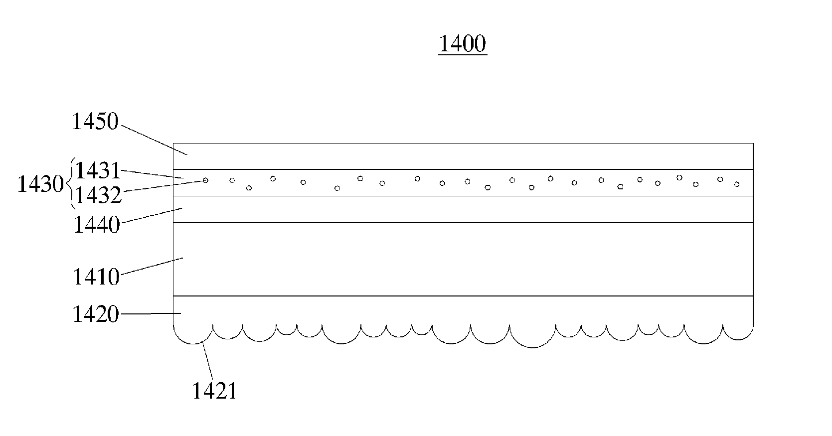
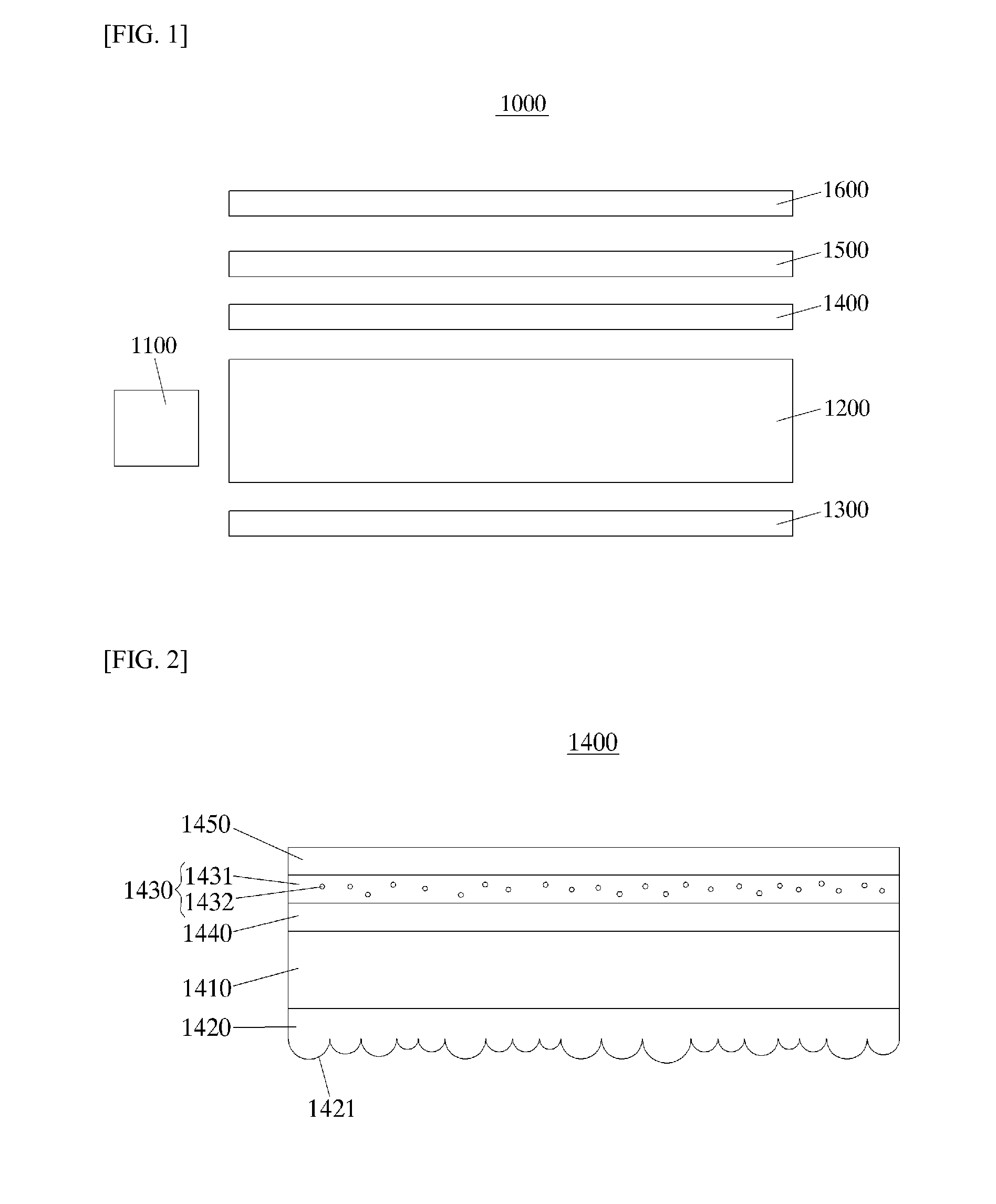
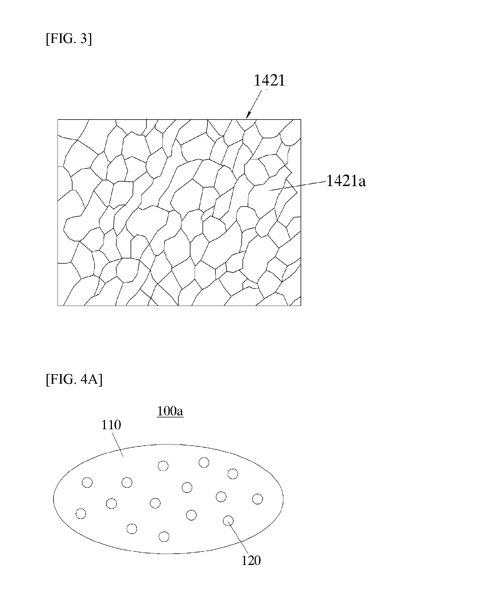
In an optical sheet and a backlight unit comprising same, the optical sheet comprises: a first transparent film, a first barrier layer; and an light conversion layer, wherein the first barrier layer is formed on one surface of the first transparent film, the light conversion layer is formed on top of the first barrier layer, and wherein at least one of a light-emitting composite including a wax particle and a nano light-emitting body that is disposed inside the wax particle, and a fluorescent particle is dispersed.

Description

CROSS-REFERENCE TO RELATED APPLICATION[0001]This application claims priority to Korean Patent Application No. 10-2012-0126925 filed on Nov. 9, 2012 and Korean Patent Application No. 10-2013-0076314 filed on Jul. 1, 2013, and all the benefits accruing therefrom under 35 U.S.C. §119, the contents of which are incorporated by reference in their entirety.BACKGROUND[0002]1. Field of the Invention[0003]The present invention relates to an optical sheet and a backlight unit including the same, and more particularly, to an optical sheet for a display device and a backlight unit including the same.[0004]2. Discussion of Related Art[0005]Nano light-emitting bodies including quantum dots, which are materials having a crystal structure of several to several tens of nanometers in size, comprise several hundred to several thousand atoms. Even when nano light-emitting bodies are formed with the same materials, the band gaps increase as the sizes of the nano light-emitting bodies decrease, and thus ...

Claims


Application Information

Patent Timeline
Patent Type & Authority Applications(United States)
IPC IPC(8): F21V8/00G02B5/02G02B5/20
CPCG02B6/005G02B5/201G02B5/0221G02B6/0051G02B6/0053G02B5/0278G02B6/0065C09K11/02C09K11/025C09K11/7706C09K11/883H01L33/507F21V3/049H01L33/56
Inventor CHOI, JEONG OGKWON, OH KWANKIM, BYEONG CHEOL
Owner LMS
Learn More