Methods, Systems, and Devices for Designing and Manufacturing Flank Millable Components

a technology of flank milling and components, applied in the direction of electric programme control, instruments, program control, etc., can solve the problems of difficult or impossible design of a component that cannot be flank milled, state of the art turbomachinery components often have very complex shapes, and can only be used to machine certain geometries

Active Publication Date: 2015-10-22
CONCEPTS ETI
View PDF8 Cites 17 Cited by
  • Summary
  • Abstract
  • Description
  • Claims
  • Application Information

AI Technical Summary

Benefits of technology

[0006]In another implementation, the present disclosure is directed to a machine-readable medium containing non-transitory machine-executable instructions for a turbomachinery component computer automated design (CAD) program. The machine-readable medium includes a blade geometry program for specifying a blade geometry including a blade surface defined by geometry quasi-orthogonal (QO) lines extending between hub and shroud sections; and an edge geometry program for specifying a flank-millable rounded edge, the edge geometry program including instructions for: receiving a user-specified edge shape selection; and generating an edge shape distribution having an edge transition that is substantially aligned with one or more of the blade surface QO lines.

Problems solved by technology

Flank milling, however, can only be used to machine certain geometries and state of the art turbomachinery components often have very complex shapes.
This high degree of flexibility can lead to the design of a component that will be difficult or impossible to flank mill.
The designer, however, may not realize he or she has designed a component that cannot be flank milled until very late in the design process, for example, not until prototyping or manufacturing.
At that point the designer is in an undesirable position choosing between proceeding with a less efficient and more costly manufacturing process such as point milling, or going back and re-designing the component.
And even if a flank millable geometry is input into the CAM software, the machine instructions calculated by the CAM program can result in excessive machine motion and undesirably long machining times.

Method used


Image

  • Methods, Systems, and Devices for Designing and Manufacturing Flank Millable Components
  • Methods, Systems, and Devices for Designing and Manufacturing Flank Millable Components
  • Methods, Systems, and Devices for Designing and Manufacturing Flank Millable Components

Examples


Embodiment Construction

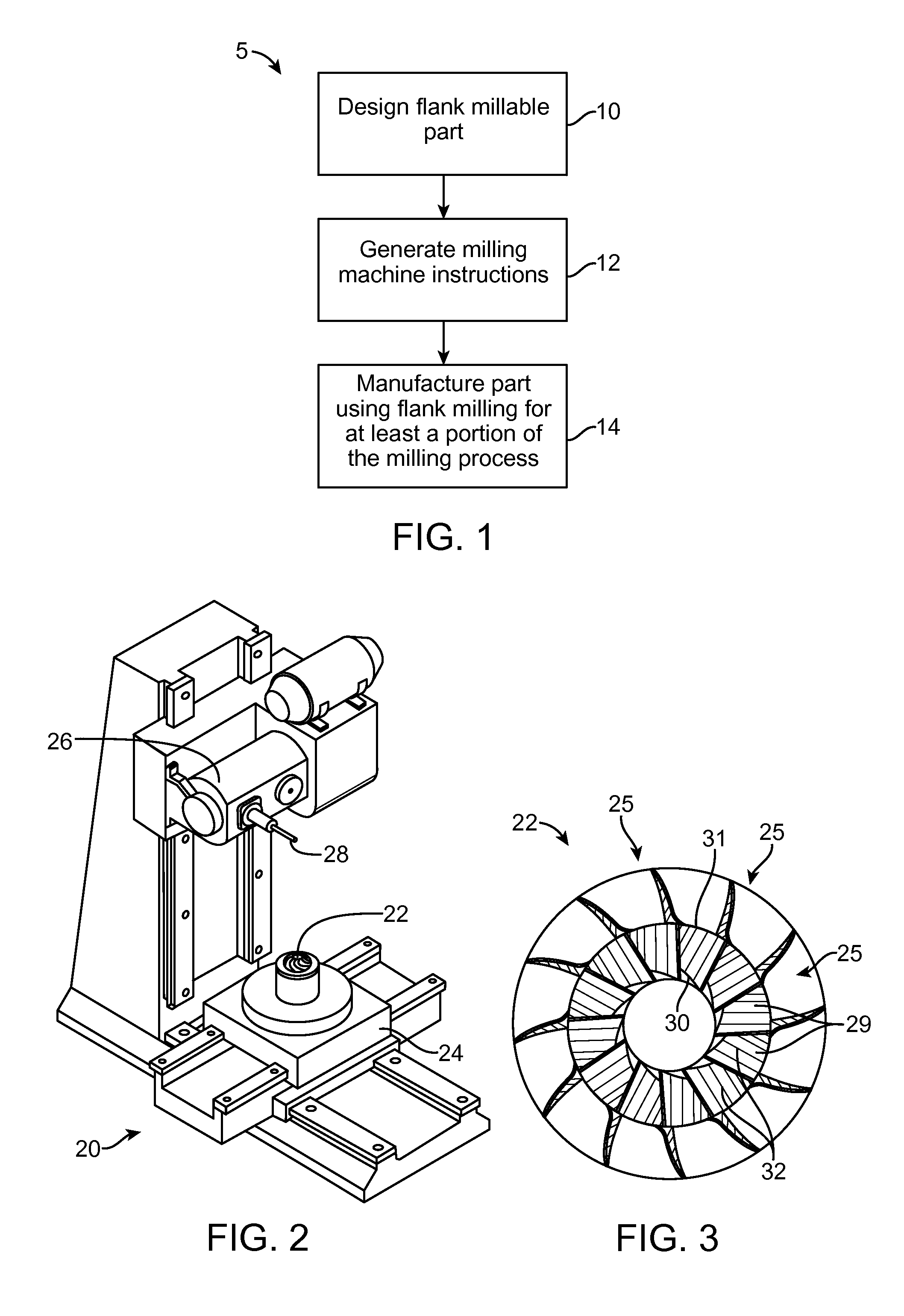
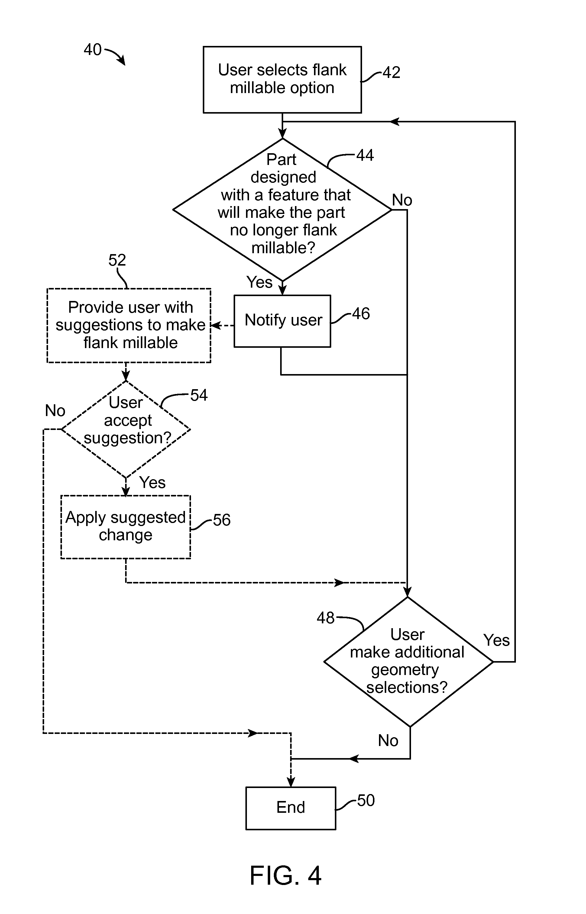
[0047]Some aspects of the present invention include devices, methods, and systems for designing a component that can be machined, at least in part, with a flank milling machining process. Methods of designing a flank millable component include monitoring component geometry options selected by a designer and notifying the designer when a geometry option is selected that will result in the component no longer being flank millable. Other aspects include providing the designer with options to modify the component geometry to make the component flank millable. As will be seen below, such feedback during the design process can be invaluable, ensuring the final component design will be flank millable and avoiding the undesirable situation of not learning until too late in the product design phase that a component cannot be flank milled. Other aspects of the present invention include improved methods of calculating flank milling machining instructions that determine an optimized machining p...


PUM

PropertyMeasurementUnit
edge shape distributionaaaaaaaaaa
edge shapeaaaaaaaaaa
shape distributionaaaaaaaaaa

Abstract

Methods, systems, and devices for designing and manufacturing flank millable components. In one embodiment, devices, systems, and methods for designing a flank millable component are provided, in which a user is notified when a component geometry option is selected that will result in the component not being flank millable. In another embodiment, the user is prevented from selecting a geometry option that would result in the component not being flank millable. In yet another embodiment, devices, systems, and methods are provided for manufacturing a component with a flank milling process, in which optimized machine instructions are determined that minimize milling machine motion.

Description

RELATED APPLICATION DATA[0001]This application is a non-provisional of U.S. Provisional Patent Application Ser. No. 61 / 982,609, filed Apr. 22, 2014, entitled “Methods, Devices, and Systems for Flank Milling a Turbo-Machinery Component,” which is incorporated by reference herein in its entirety.FIELD OF THE INVENTION[0002]The present invention generally relates to the field of design and manufacture of turbomachinery components. In particular, the present invention is directed to the design of flank millable turbomachinery components and methods of determining milling instructions for flank milling turbomachinery components.BACKGROUND[0003]Turbomachinery components can be designed using computer automated design (CAD) software to generate a dataset representing the shape of the component. Computer automated manufacturing (CAM) software can then be used to translate the data set into a series of machining instructions for manufacturing the component.[0004]Turbomachinery components are...

Claims


Application Information

Patent Timeline
Patent Type & Authority Applications(United States)
IPC IPC(8): G05B19/4099B23C3/00G05B19/18F01D5/14G06F3/0484
CPCG05B19/4099F01D5/147G06F3/04842B23C2215/44B23C3/00G05B2219/37355G05B19/182B23C3/18F01D5/048F05D2230/10G05B19/4068G05B2219/35287Y10T409/303752Y10T409/305656B23C2220/04G06F30/00G06F2119/18
Inventor COOPER, DEREK J.PLOMP, ALEXANDERJAPIKSE, DAVID
Owner CONCEPTS ETI
Why Eureka
Try Eureka