

Cable switch
a cable switch and switch technology, applied in the direction of electric switches, contact mechanisms, electrical apparatus, etc., can solve the problems of switch operation in an unintended way, switch resistance reduction, listener may feel the operation cumbersome, etc., and achieve the effect of easy production
- Summary
- Abstract
- Description
- Claims
- Application Information
AI Technical Summary
Benefits of technology
Problems solved by technology
Method used
Image

Examples
first embodiment
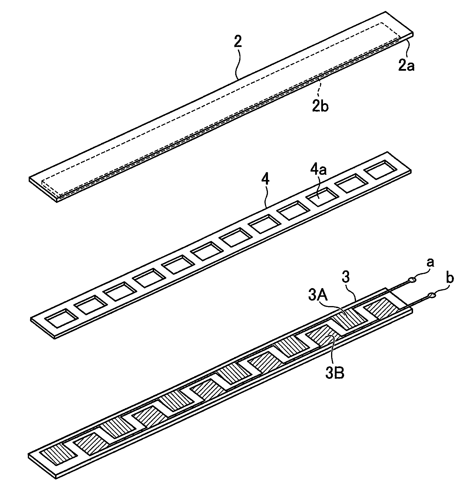
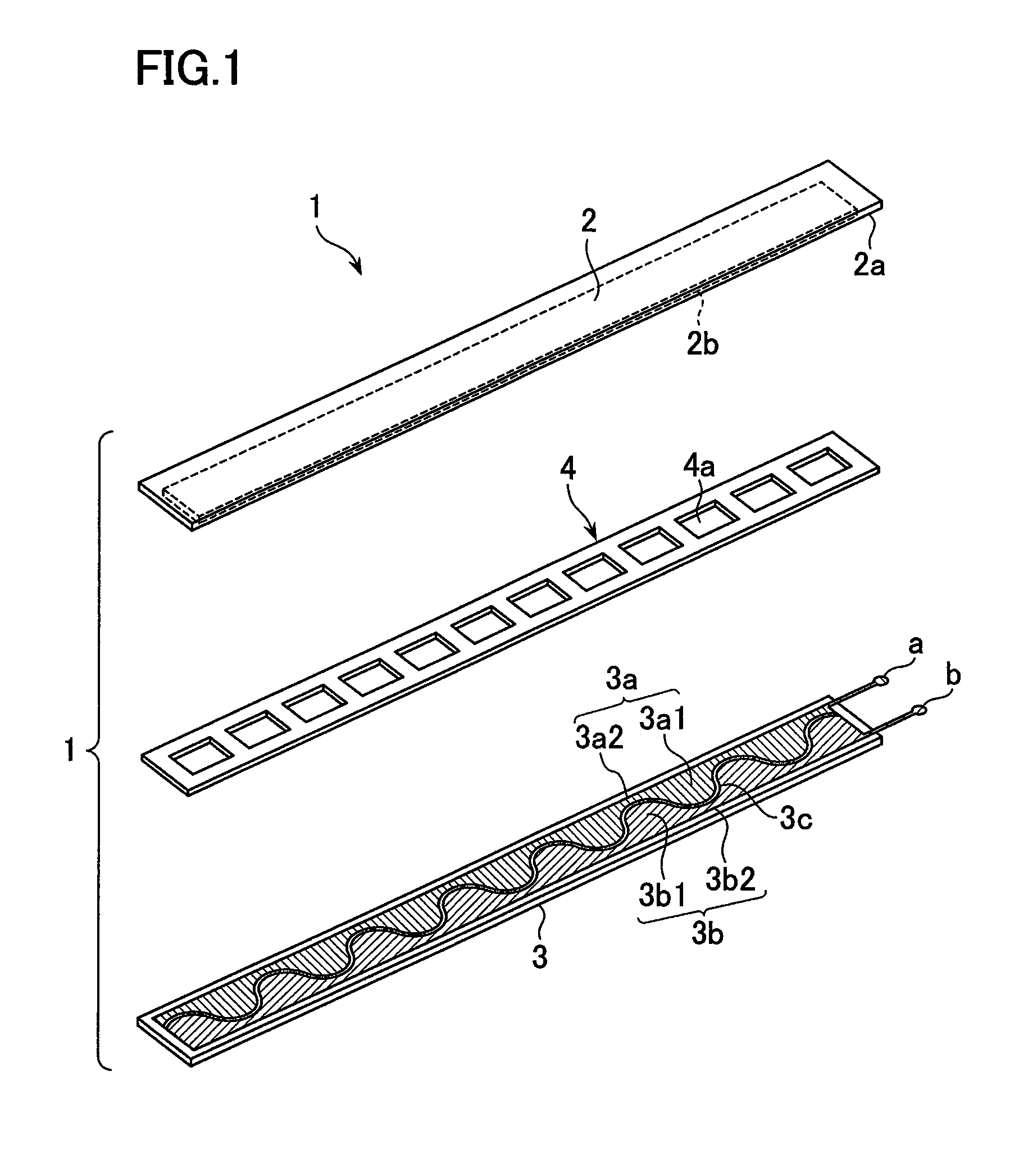
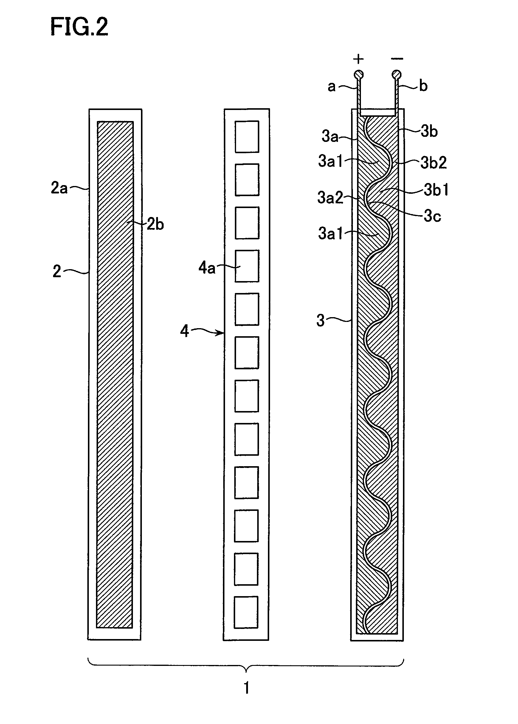
[0051]FIG. 1 is an exploded perspective view of a flat cable switch according to the present invention. FIG. 2 is a plan view of main constituent elements of the cable switch according to the present invention
[0052]A cable switch 1 according to the present invention includes a first base material 2 of a an elongated band shape, a second base material 3 of the same shape as that of the first base material 2 and arranged to face the first base material 2 and to be distanced from the first base material 2, and a spacer 4 of a band shape provided to be sandwiched between these first and second base materials 2 and 3.
[0053]The first base material 2 is constituted by an insulating material 2a made of, for example, a flexible polyester film and a conductor 2b provided on an inner surface of the insulating material 2a by printing. This conductor 2b is formed to be slightly smaller than the insulating material 2a. To help understand this, FIG. 2 shows the first base material 2 in a planar st...
second embodiment
[0086]FIG. 17 is an exploded perspective view of main constituent elements according to the present invention. FIG. 18 is a plan view of the respective constituent elements.
[0087]In this embodiment, similarly to the first embodiment, the positive electrode 3a and the negative electrode 3b are formed into convex and concave shapes; however, specific shapes of the concave and convex portions are rectangular shapes.
[0088]That is, as shown in FIG. 18 in detail, the positive electrode 3A includes a linear portion 3c extending in the length direction along one side of the second base material 3, and convex portions 3d provided protruding at predetermined intervals along a length direction of this linear portion 3c. Each of these convex portions 3d protrudes toward the negative electrode 3B that is arranged to face the positive electrode 3A and is formed into a rectangular shape. Concave portions 3e are formed between the adjacent convex portions 3d provided protruding along the length dir...
third embodiment
[0099]FIG. 28 is a partial plan view of main constituent elements according to the present invention. FIG. 29 is a partial plan view in a partially assembled state.
[0100]This embodiment is characterized as follows. A positive electrode 3C and a negative electrode 3D provided on the inner surface of the second base material 3 are simple in shape, that is, of linear shapes. An insulating gap 3J between the positive electrode 3C and the negative electrode 3D is also of a linear shape.
[0101]If the linear constituent elements are used in the second base material 3, it is advantageously possible to facilitate manufacturing as compared with the configuration in which the corrugated or rectangular electrodes are used and alternately arranged to face each other as described in the first and second embodiments.
[0102]In this embodiment, a width of the positive electrode 3C is smaller than that of the negative electrode 3D. Therefore, the gap 3J is at an offset position from the central positio...
PUM
 Abstract
Description
Claims
Application Information