The engine-driven generator rotational speed control method

Inactive Publication Date: 2015-10-22
SHANGHAI HUAXING DIGITAL TECH +1
View PDF13 Cites 0 Cited by
  • Summary
  • Abstract
  • Description
  • Claims
  • Application Information

AI Technical Summary

Benefits of technology

This patent describes a method for controlling the speed of an engine-driven generator to improve its performance and longevity. The method uses a dynamic discrete method to determine the optimal speed of the generator to ensure the voltage output is dynamic and responsive. This allows the generator to work more efficiently and increases its service life.

Problems solved by technology

In order to solve the problems that the adjustment of current engine-driven generator objective speed without considering the operating state of the generator, this issue will affect the responsiveness of the DC output voltage of the generator, and the engine output margin without taking the mutual influence among DC output voltage of the generator, rotational speed of the generator and generator excitation current into consideration, as well as the generator objective conduction angle settings complex, inconvenient adjustment problems.

Method used


Image

  • The engine-driven generator rotational speed control method
  • The engine-driven generator rotational speed control method
  • The engine-driven generator rotational speed control method

Examples


Embodiment Construction

[0031]To make the objective, technical solutions and advantages of the present invention more apparent, the Embodiment of the present invention will be further illustrated in combination with the drawings.

[0032]The embodiments of the present invention provide an engine-driven generator rotational speed control method, the generator equivalent excitation current IA, the objective DC output voltage of the generator (DCLV) and the actual rotational speed of the generator n so as to determine the current operating state.

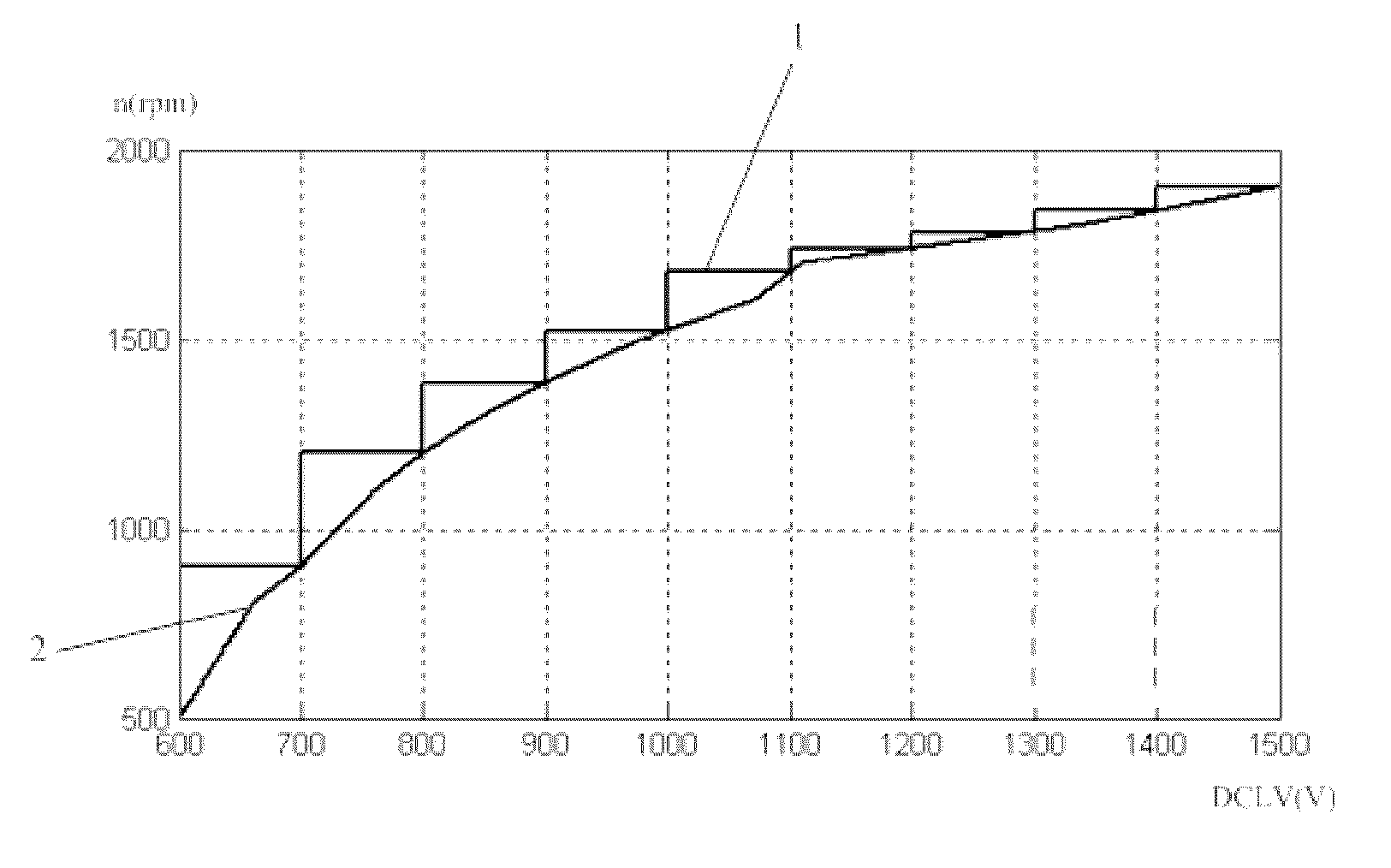
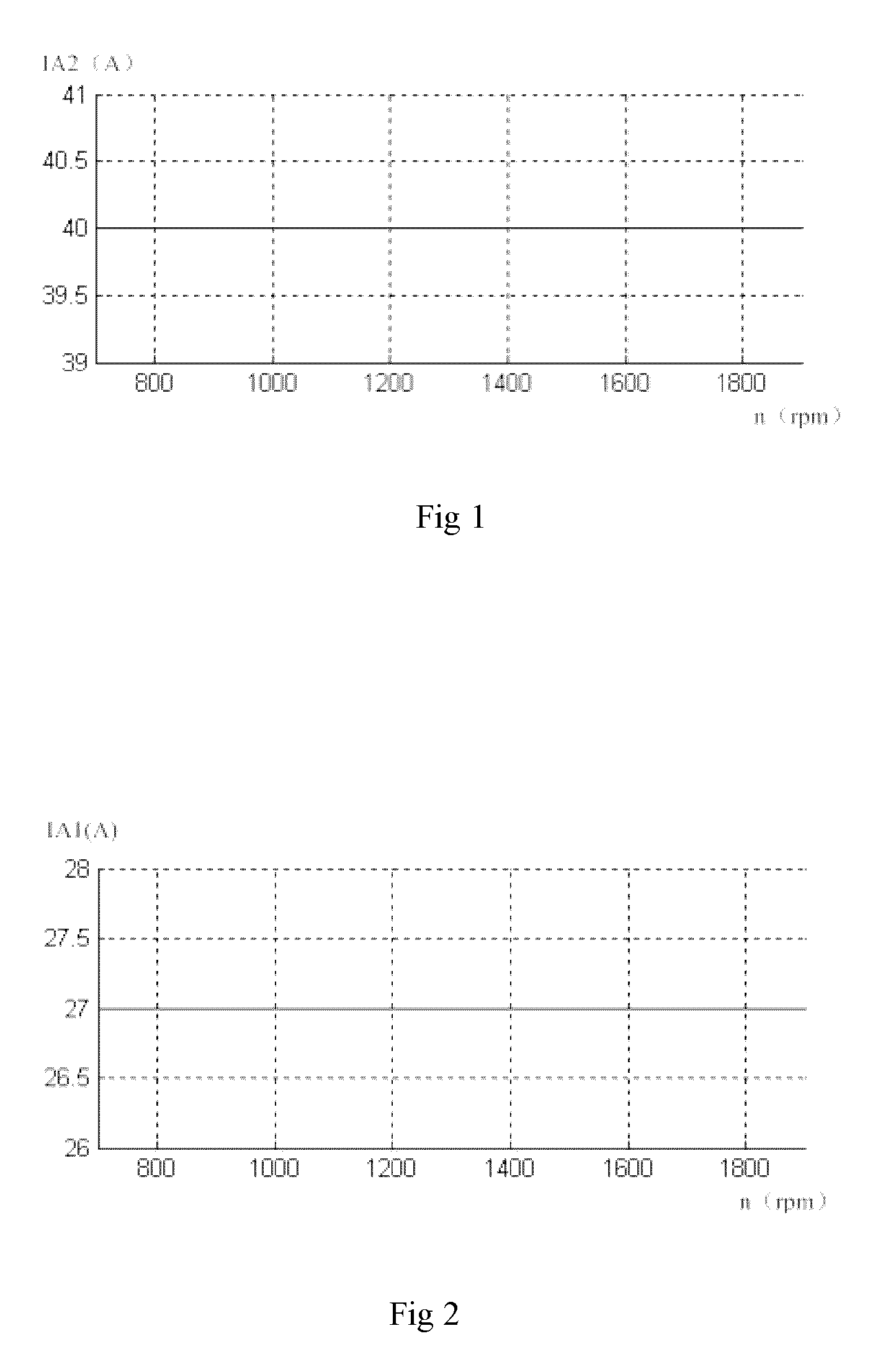
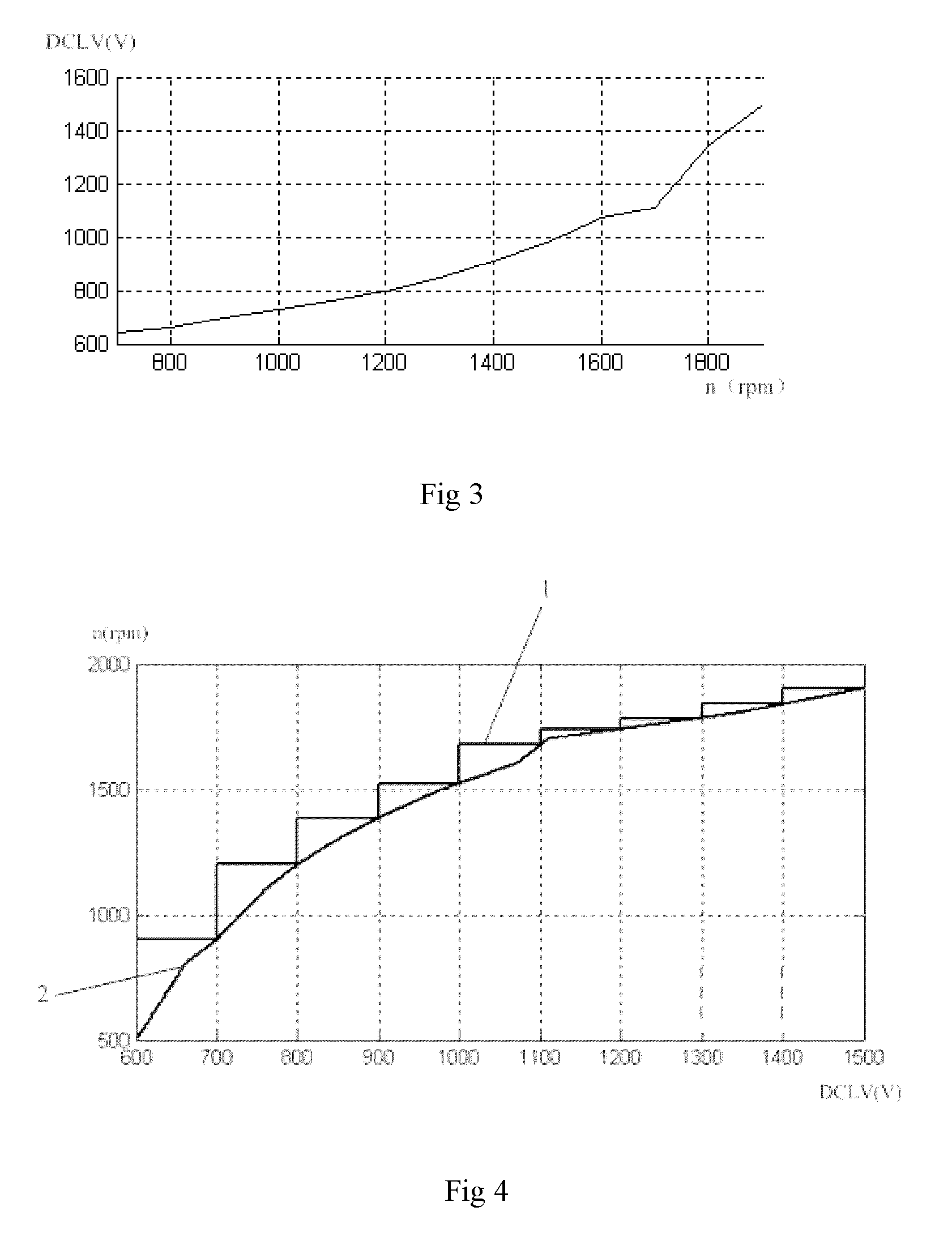
[0033]Firstly, for determining the current operating state area of the generator, the generator open-loop characteristic curve is used for obtaining the curves in FIG. 1, FIG. 2 and FIG. 3. FIG. 1 (n-IA2) shows the critical line between the depth of the saturation area and the transition area on the generator open-loop characteristic curve, and FIG. 2 (n-IA1) and FIG. 3 (n-DCLV) shows the critical line between the linear area and the transition area on the generator open...


PUM


Abstract

This present invention discloses an engine-driven generator rotational speed control method. The method comprises the following steps, obtaining n-IA1 curve, n-IA2 curve, n-DCLV curve and DCLV-n curve through the generator open-loop characteristic curve; determining whether the current work area of the generator is the saturation area, the transition area or the linear area, and meanwhile determining the 1.1-times DCLV work area. The present invention adjusts the generator objective rotational speed by determining the state of the generator, and outputs the generator objective rotation rotational speed by the method of dynamic discrete, so as to ensure the responsiveness of the DC output voltage of the generator, to extend the service life of the generator, and to make the generator work in a more efficient state.

Description

CROSS-REFERENCE TO RELATED APPLICATIONS[0001]The present application claims the priority of the Chinese application number 201210357599.5, filed on Sep. 24, 2012, the disclosure of which is herewith incorporated by reference in its entirety.TECHNICAL FIELD[0002]The present invention relates to the technical field of the engine-driven generator, and particularly to an engine-driven generator rotational speed control method.BACKGROUND OF THE TECHNICAL[0003]The engine operating state is the main reference to the adjustment of the engine-driven generator objective rotational speed, i.e. the objective engine speed is adjusted according to the engine load and engine operating environment (temperature, atmospheric pressure, etc.).[0004]An current engine-driven generator is capable of providing output margin which responses quickly for load changes. The objective conduction angle is set to less than the maximum conduction angle range by adjusting the objective conduction angle, which makes ...

Claims


Application Information

Patent Timeline
IPC IPC(8): H02P9/04
CPCH02P9/04
Inventor WANG, JIANMINGLIAO, XIAOMING
Owner SHANGHAI HUAXING DIGITAL TECH
Why Eureka
Try Eureka