Relay communication system and relay communication device

a relay communication and communication system technology, applied in the field of relay communication system and relay communication device, can solve the problems of inability to ensure responsiveness, data transmission takes time, and apparatuses performing such wireless communication cannot perform normal communication, so as to achieve the effect of preventing transmission collision and reducing cos

Inactive Publication Date: 2014-01-02
MURATA MASCH LTD
View PDF5 Cites 6 Cited by
  • Summary
  • Abstract
  • Description
  • Claims
  • Application Information

AI Technical Summary

Benefits of technology

[0022]In this configuration, since the communication control device transfers the data transmitted by each relay communication device in an integrated manner, transmission collision can be reliably prevented. According to another preferred embodiment of the present invention, a relay communication device with the following configuration is provided. That is, a relay communication device includes an operation mode setting unit, a first communication unit, a second communication unit, a communication buffer, a transmission data processing unit, a received data processing unit, a polling processing unit, a transmission permission granting unit, and a polling restart processing unit. The operation mode setting unit sets whether to function as a communication control device or a slave device. The first communication unit communicates with a terminal device connected thereto. The second communication unit communicates with another relay communication device. The communication buffer temporarily accumulates data received via the first communication unit. The transmission data processing unit starts, in the case of functioning as the slave device, transmitting the data accumulated in the communication buffer from the second communication unit in accordance with transmission permission from a relay communication device functioning as the communication control device and limits the amount of the data allowed to be transmitted with one transmission permission to a predetermined amount of the data or less. The received data processing unit transmits, in the case where a destination of the data received via the second communication unit is the terminal device connected thereto, the data from the first communication unit. The polling processing unit transmits to the relay communication device functioning as the slave device an inquiry signal that inquires whether or not data has accumulated in the communication buffer in a predetermined order in a case of functioning as the communication control device. The transmission permission granting unit interrupts the inquiry by the polling processing unit and transmits the transmission permission to one of the plurality of relay communication devices that has returned the reply in the case of functioning as the communication control device and receives from the relay communication device the reply indicating that data has accumulated in the one of the plurality of relay communication devices to which the inquiry signal has been transmitted. The polling restart processing unit causes the polling processing unit to restart the inquiry into the next relay communication device after transmission of the data is completed in the case of functioning as the communication control device.
[0023]Since the relay communication device is configured to be capable of functioning also as the communication control device, cost can be reduced by commonly providing the hardware, enabling a flexible configuration of the relay communication system.

Problems solved by technology

Apparatuses performing such wireless communication cannot perform normal communication when transmission collision, in which a plurality of apparatuses simultaneously performs transmission, occurs.
In such a case where a wireless communication device to which transmission right is granted by the polling transmits a large amount of data, data transmission takes time so that other wireless communication devices are forced to wait for a long time period before transmitting data.
Thus, a system in which responsiveness is critical (for example, a system required to reliably perform a communication within a specific predetermined time) cannot employ the above-described configuration.
However, this configuration cannot ensure responsiveness since forcing the apparatuses to wait for transmission causes delay.
In particular, since waiting time is randomly determined, communication delay cannot be projected in advance.
In addition, the delay may be longer (i.e., the waiting time may be longer).
However, since the number of request signal slots is limited in the configuration of Japanese Unexamined Patent Publication No. 2001-86137, a larger number of the slave devices requires a larger ratio of slave devices to which the request signal slots cannot be fixedly allocated.
As a result, increase of transmission collision of request signals cannot be avoided.
As described above, regardless of using polling or not, the conventional art cannot ensure responsiveness of the system.

Method used


Image

  • Relay communication system and relay communication device
  • Relay communication system and relay communication device
  • Relay communication system and relay communication device

Examples


Embodiment Construction

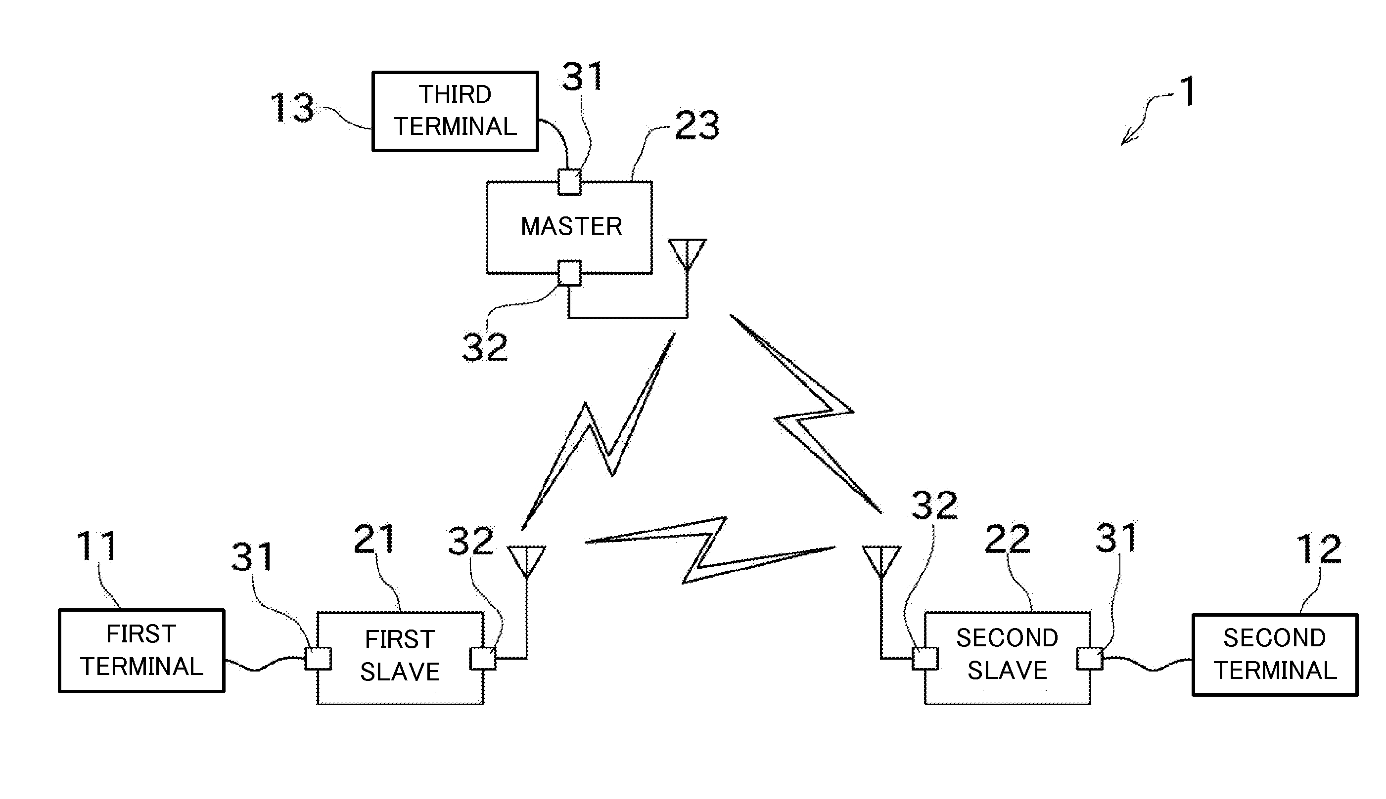
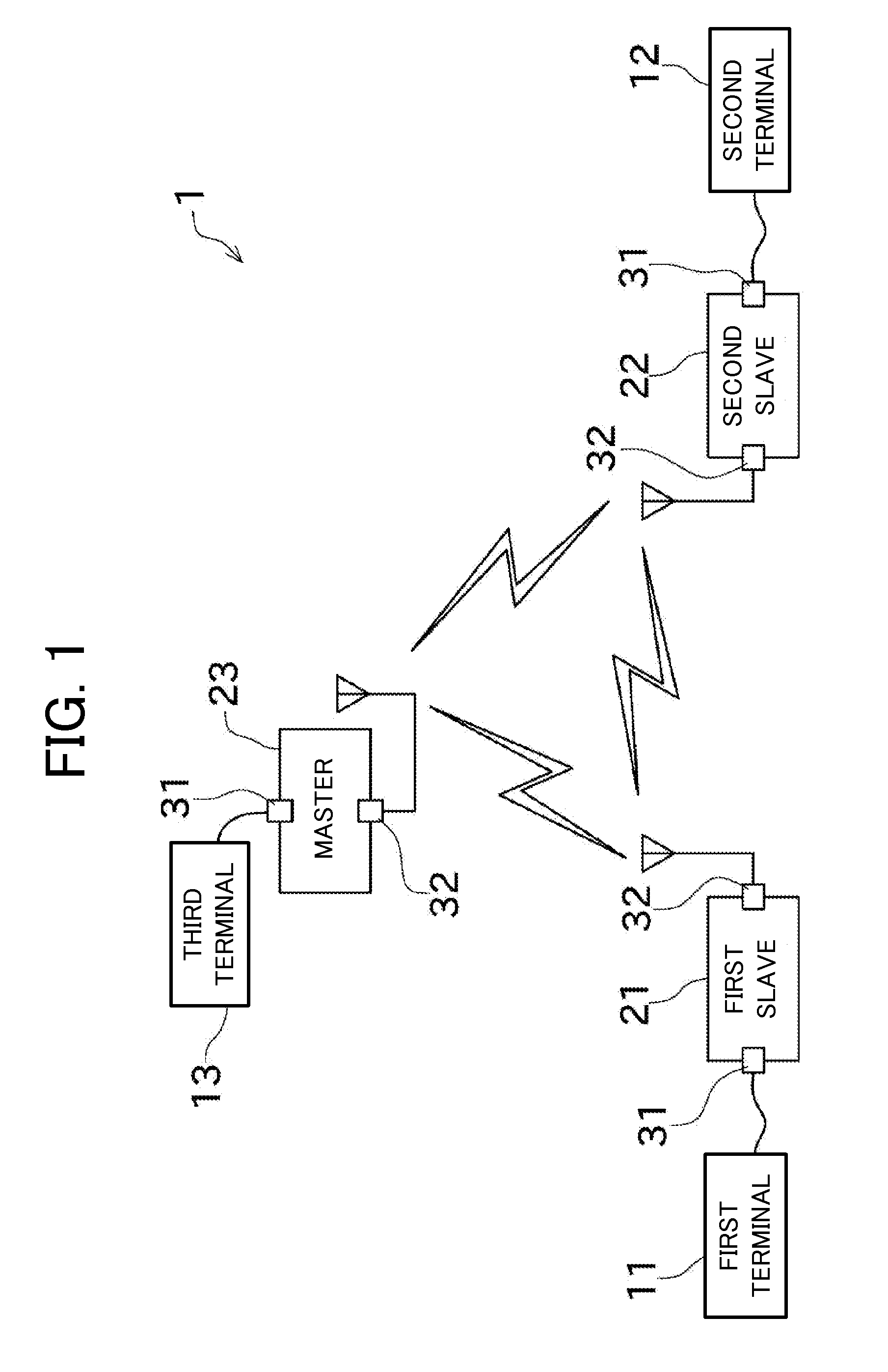
[0037]Next, preferred embodiments of the present invention will be described with reference to the drawings. An overall configuration of a relay communication system 1 according to a first preferred embodiment of the present invention is illustrated in FIG. 1.

[0038]The relay communication system preferably includes a plurality of terminal devices 11, 12, and 13. The terminal devices 11, 12, and 13 are apparatuses designed on a condition that the terminal devices 11, 12, and 13 preferably communicate with each other by wired serial communication such as, for example, RS-232C or CAN. Although three terminal devices (a first terminal 11, a second terminal 12, and a third terminal 13) are preferably included in a non-limiting example of FIG. 1, which is a minimum configuration, the relay communication system 1 may include four or more terminal devices, for example.

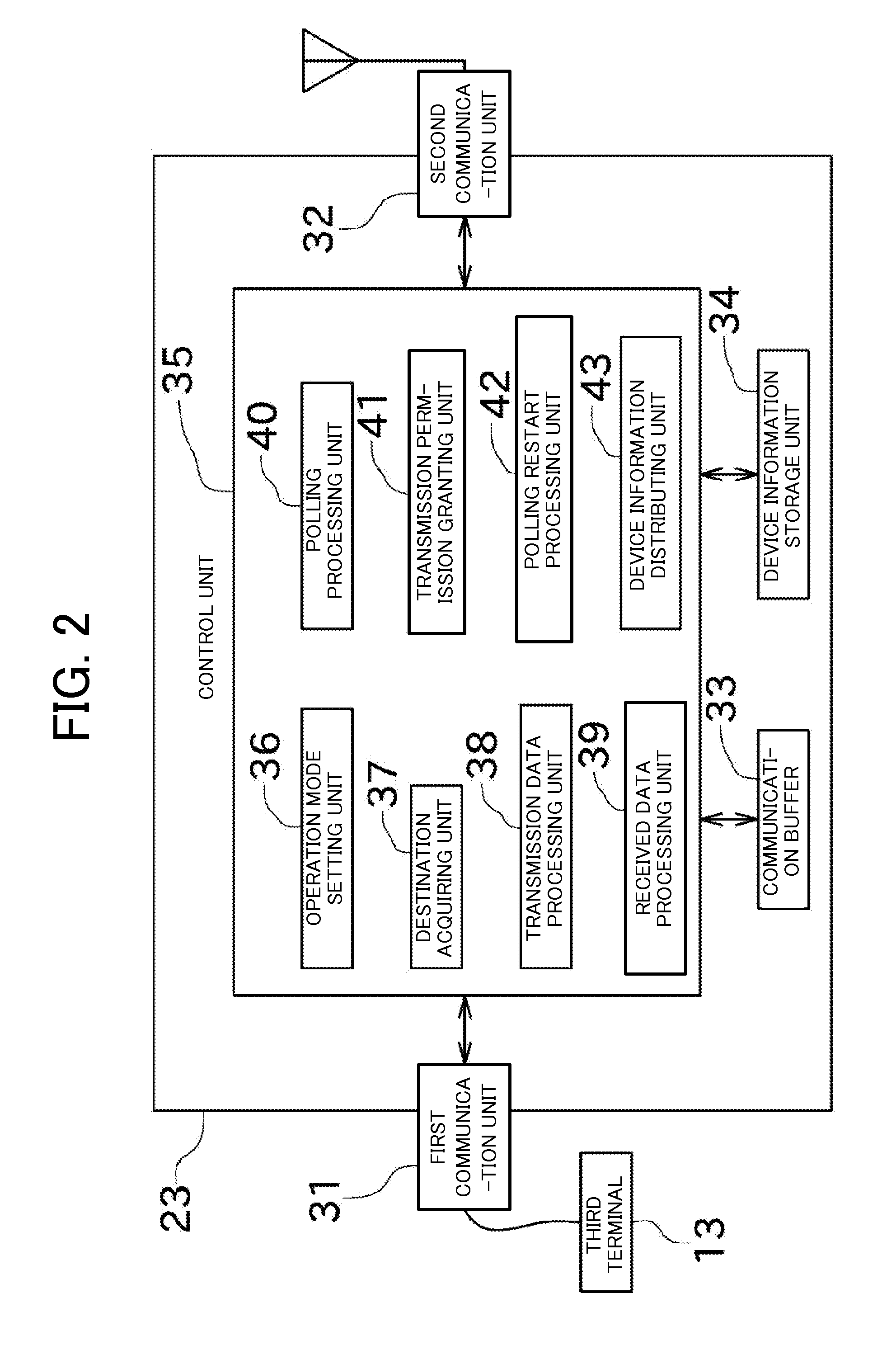
[0039]Each terminal device 11, 12, and 13 is wire-connected to a relay communication device. The relay communication device ...


PUM


Abstract

A relay communication device includes a first communication unit, a second communication unit, and a communication buffer. When receiving data in the first communication unit, each relay communication device temporarily accumulates the data in the communication buffer. The relay communication device functioning as a master asks the relay communication device functioning as a slave if there is data in the communication buffer. The master grants transmission permission to the slave that has returned a reply indicating that there is data. The slave that has received the transmission permission transmits the data to a slave that is a destination of the data. The master makes an inquiry into a next slave in the case where the slave which has been granted the transmission permission completes the transmission of the data from the second communication unit. The allowed amount of data transmitted by each relay communication device at one time is limited.

Description

CROSS-REFERENCE TO RELATED APPLICATIONS[0001]This application claims priorities under 35 U.S.C. 119 to Japanese Patent Application Nos. 2012-144741 and 2012-144743 filed on Jun. 27, 2012, and 2013-28369 filed on Feb. 15, 2013, which applications are hereby incorporated by reference in their entirety.BACKGROUND OF THE INVENTION[0002]1. Field of the Invention[0003]The present invention relates to a configuration for avoiding transmission collision in a relay communication system that allows relay communication devices to communicate with each other.[0004]2. Description of the Related Art[0005]There has been known an adapter that transforms serial communication such as RS-232C or CAN (Controller Area Network) into wireless communication. Transforming communication between devices that had been connected to each other by wire into wireless provides such technical advantages as being cableless.[0006]Apparatuses performing such wireless communication cannot perform normal communication wh...

Claims


Application Information

Patent Timeline
Patent Type & Authority Applications(United States)
IPC IPC(8): H04W16/26
CPCH04W16/26H04B7/15557H04B7/2606
Inventor TANIMOTO, YOSHIFUMI
Owner MURATA MASCH LTD
Why Eureka
Try Eureka