Multi-branch outphasing system and method

Active Publication Date: 2015-10-22
TEXAS INSTR INC
View PDF7 Cites 12 Cited by
  • Summary
  • Abstract
  • Description
  • Claims
  • Application Information

AI Technical Summary

Benefits of technology

The invention aims to improve the power efficiency of multi-level outphasing power amplifiers operating at large "back-off" power levels. It provides a way to achieve improved power efficiency without requiring multiple power supply levels or generating and switching between them to provide operating supply voltage and power to the internal power amplifiers of the multi-level outphasing power amplifiers. This invention simplifies the implementation of multi-level outphasing power amplifiers and improves their overall performance.

Problems solved by technology

A problem of the prior art is that the need for high data rates and efficient spectrum utilization in modem wireless communication systems results in high peak-to-average power ratios of modulated signals.
Traditional power amplifiers have much lower efficiency (i.e., power delivered by the amplifier to the load divided by total power consumed by the power amplifier) under large power back-off conditions than under peak output power conditions.
In handheld devices, low power efficiency of the RF power amplifiers results in shorter battery lifetimes, and in base station applications the low power efficiency of the RF power amplifiers may result in wasted power and high heat sinking costs.
Unfortunately, generating the multiple power supply levels and switching among them is undesirably / unacceptably power consuming and also is relatively difficult to implement.
Another approach is to vary RF carrier signal duration, but this also causes undesirably high power consumption and is difficult to control.
Increasing the phase difference θ between the driving signals S1(t) and S2(t) results in a reduction in power efficiency.
When the outputs of two such power amplifiers are combined or added together, there may be substantial power loss in the combiner which reduces efficiency, and the efficiency decreases as the output / load power decreases.
In basic outphasing, a large phase difference between S1(t) and S2(t) (when low power is required at the load) results in power dissipation in the combiners.
Consequently, power efficiency is reduced when power delivered to the load decreases.
Although this increases power efficiency compared to that of basic outphasing, the Godoy et. al technique has other shortcomings, including the fact that generation of multiple power supply levels is difficult and costly, the switching results in losses that reduce power efficiency, and synchronization problem between power supply switching and RF signal paths results in signal nonlinearity.

Method used


Image

  • Multi-branch outphasing system and method
  • Multi-branch outphasing system and method
  • Multi-branch outphasing system and method

Examples


Embodiment Construction

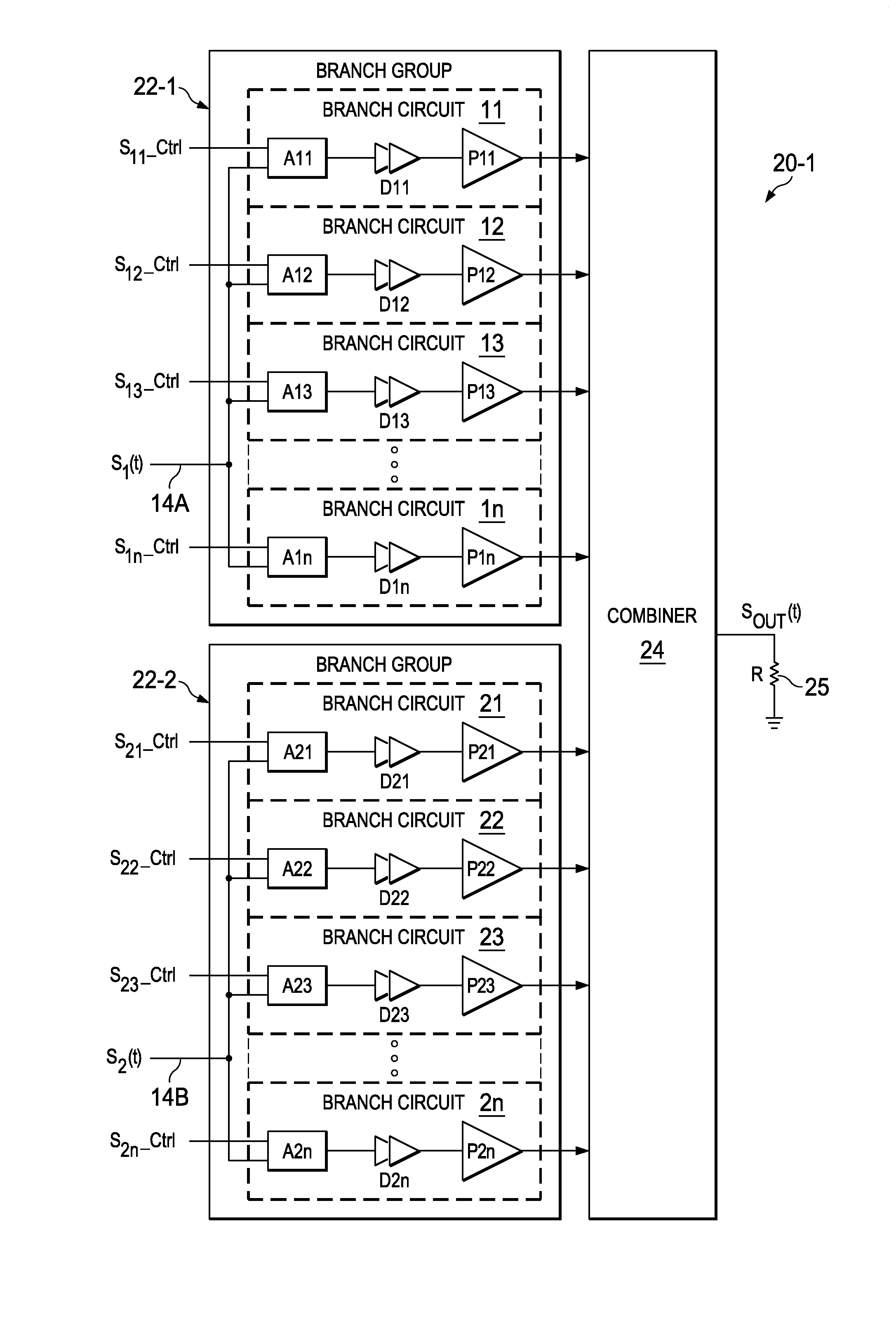
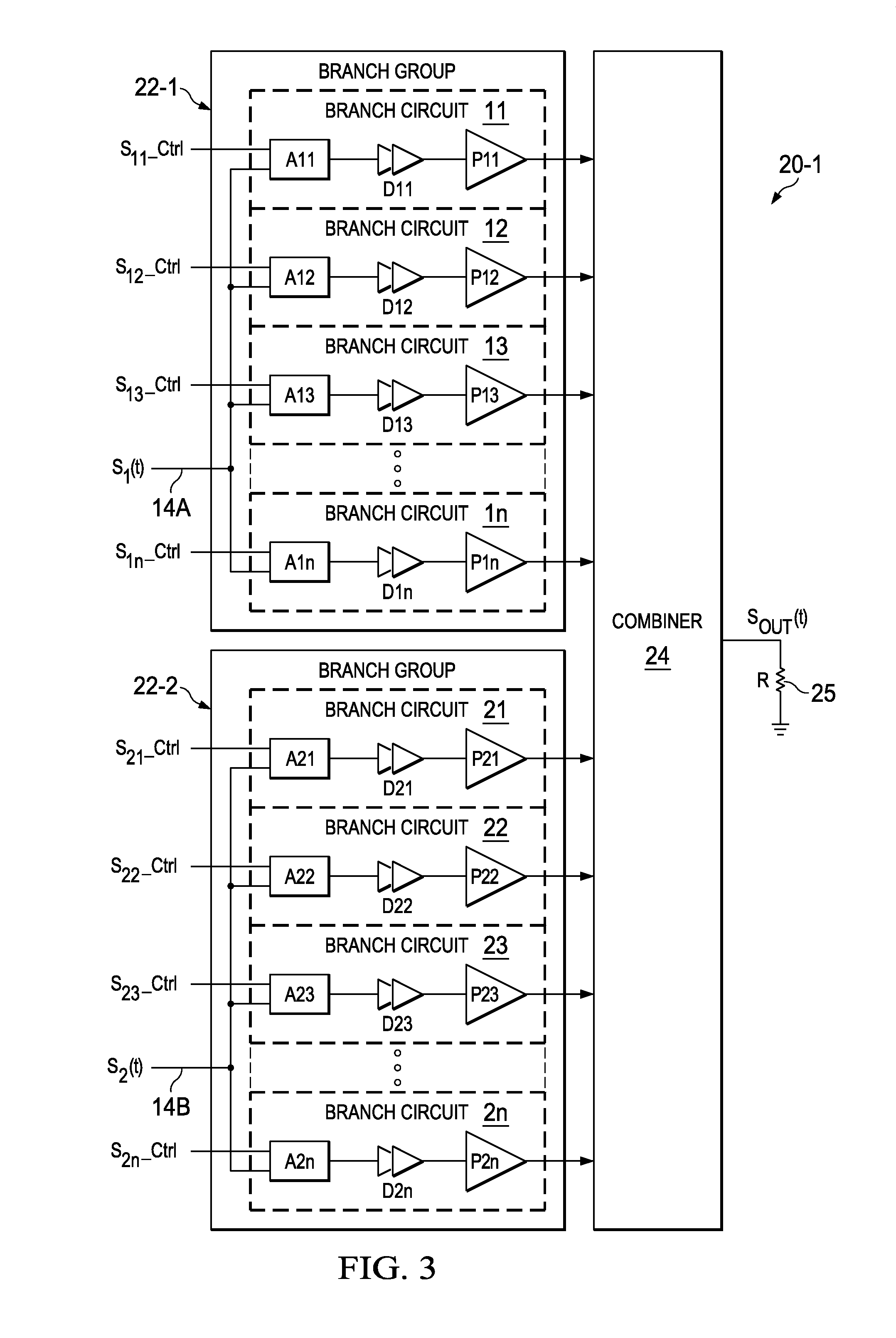
[0052]An asymmetric multi-level, multi-branch outphasing power amplifier includes multiple circuits, each of which includes a power amplifier (such as a class-E power amplifier) and combiner circuitry coupled to the output of that power amplifier. A first RF drive signal is coupled to inputs of all the power amplifiers of a first group of branch circuits, and a second RF drive signal is coupled to inputs of all of the power amplifiers of a second group of branch circuits. In one embodiment, each branch circuit of the first group includes an enable circuit or activation circuit that couples or enables the first drive signal to the inputs of the various power amplifiers in the first group of branch circuits in response to a first group of corresponding selection control signals. Similarly, each branch circuit of the second group includes an enable circuit or activation circuit that couples the second drive signal to the inputs of the various power amplifiers in the second group of bra...


PUM


Abstract

A multi-level, multi-branch outphasing amplifier (20-1) includes a first branch group circuit (22-1) including a first branch circuit (11) receiving a first RF input signal (S1(t)) and first control information (S11<sub2>—< / sub2>Ctrl=VDD) and a second branch circuit (12) receiving the first input signal and second control information (S12<sub2>—< / sub2>Ctrl). Each of the first (11) and second (12) branch circuits includes a power amplifier. The second control information enables the second branch circuit to be switched on or off while the first branch circuit (12) remains on. A second branch group circuit (22-2) includes a third branch circuit (21) receiving a second RF input signal (S2(t)) and third control information (S21<sub2>—< / sub2>Ctrl=VDD) and a fourth branch circuit (22) receiving the second input signal (S2(t)) and fourth control information (S22<sub2>—< / sub2>Ctrl). Each of the third and fourth branch circuits includes a power amplifier. The fourth control information enables the fourth branch circuit to be switched on or off while the third branch circuit remains on. A combiner (24) combines output signals of the power amplifiers to produce an output signal (SOUT(t)).

Description

BACKGROUND OF THE INVENTION[0001]The present invention relates generally to multi-level outphasing power amplifiers, and more particularly to asymmetric multi-level, multi-branch outphasing power amplifiers which have improved power efficiency and which do not require switching between multiple power supply voltages.[0002]A problem of the prior art is that the need for high data rates and efficient spectrum utilization in modem wireless communication systems results in high peak-to-average power ratios of modulated signals. This requires associated RF power amplifiers (PAs) to operate much of the time at greatly reduced output power levels, which is referred to as large “power back-off” operation. Traditional power amplifiers have much lower efficiency (i.e., power delivered by the amplifier to the load divided by total power consumed by the power amplifier) under large power back-off conditions than under peak output power conditions.[0003]In handheld devices, low power efficiency ...

Claims


Application Information

Patent Timeline
IPC IPC(8): H04B1/16H04B1/12H04B1/18
CPCH04B1/1615H04B1/123H04B1/18H03F1/0277H03F1/0294H03F1/223H03F3/193H03F3/211H03F3/245H03F3/72H03F2200/411H03F2200/511H03F2200/541H03F2203/21136H03F2203/21142H03F2203/7215H03F2203/7236
Inventor BANERJEE, ARITRAHEZAR, RAHMIDING, LEISCHEMM, NATHAN RICHARD
Owner TEXAS INSTR INC
Why Eureka
Try Eureka