
Sensing devices

a technology of sensing device and sensor, which is applied in the field of sensing device, can solve the problems of disadvantageous sensing quality of power noise in coms image sensor, inability to filter out high-frequency noise, and inability to achieve low power noise. the effect of enhancing the sensing quality

Active Publication Date: 2015-10-22
HIMAX IMAGING LIMITED
View PDF0 Cites 8 Cited by
  • Summary
  • Abstract
  • Description
  • Claims
  • Application Information

AI Technical Summary

Benefits of technology

The patent text aims to provide a sensing device that can generate a readout signal with low power noise or without power noise, thereby improving sensing quality.

Problems solved by technology

Generally, power noise is a problem in COMS image sensors.
Especially, when CMOS image sensors operate at low light conditions, the power noise may affect disadvantageously the sensing quality.
However, when an on-chip RC filter is used, high-frequency noise is not easily filtered out.
Moreover, if an off-chip RC filter is used for a CMOS image sensor instead of on-chip RC filter, the off-chip RC filter will increases the cost of the COMOS image sensor.
However, high-frequency noise is also not easily filtered out.
Thus, the power may still contain some high-frequency noise components.

Method used


Image

  • Sensing devices
  • Sensing devices
  • Sensing devices

Examples


Embodiment Construction

[0015]The following description is of the best-contemplated mode of carrying out the invention. This description is made for the purpose of illustrating the general principles of the invention and should not be taken in a limiting sense. The scope of the invention is best determined by reference to the appended claims.

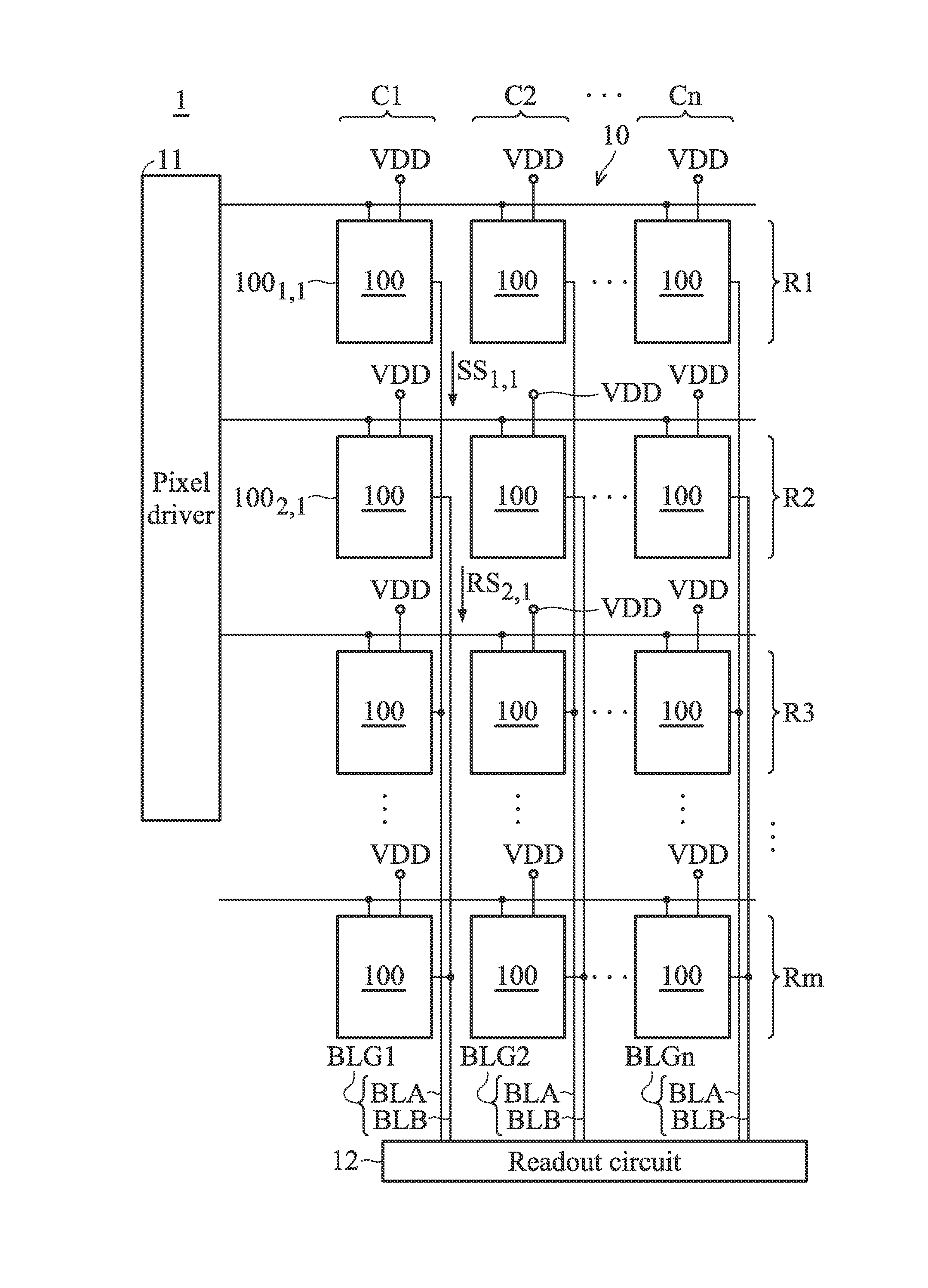
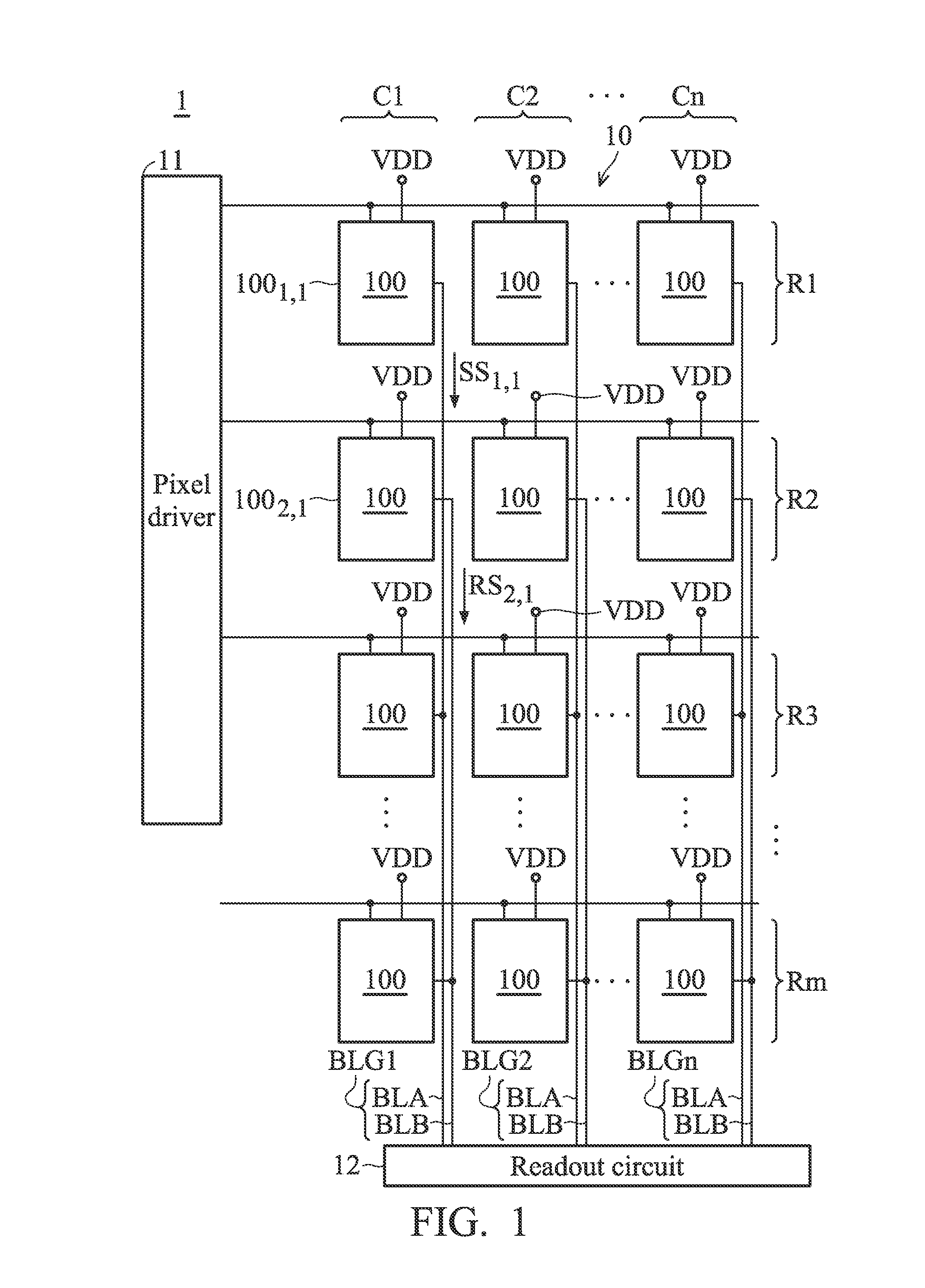
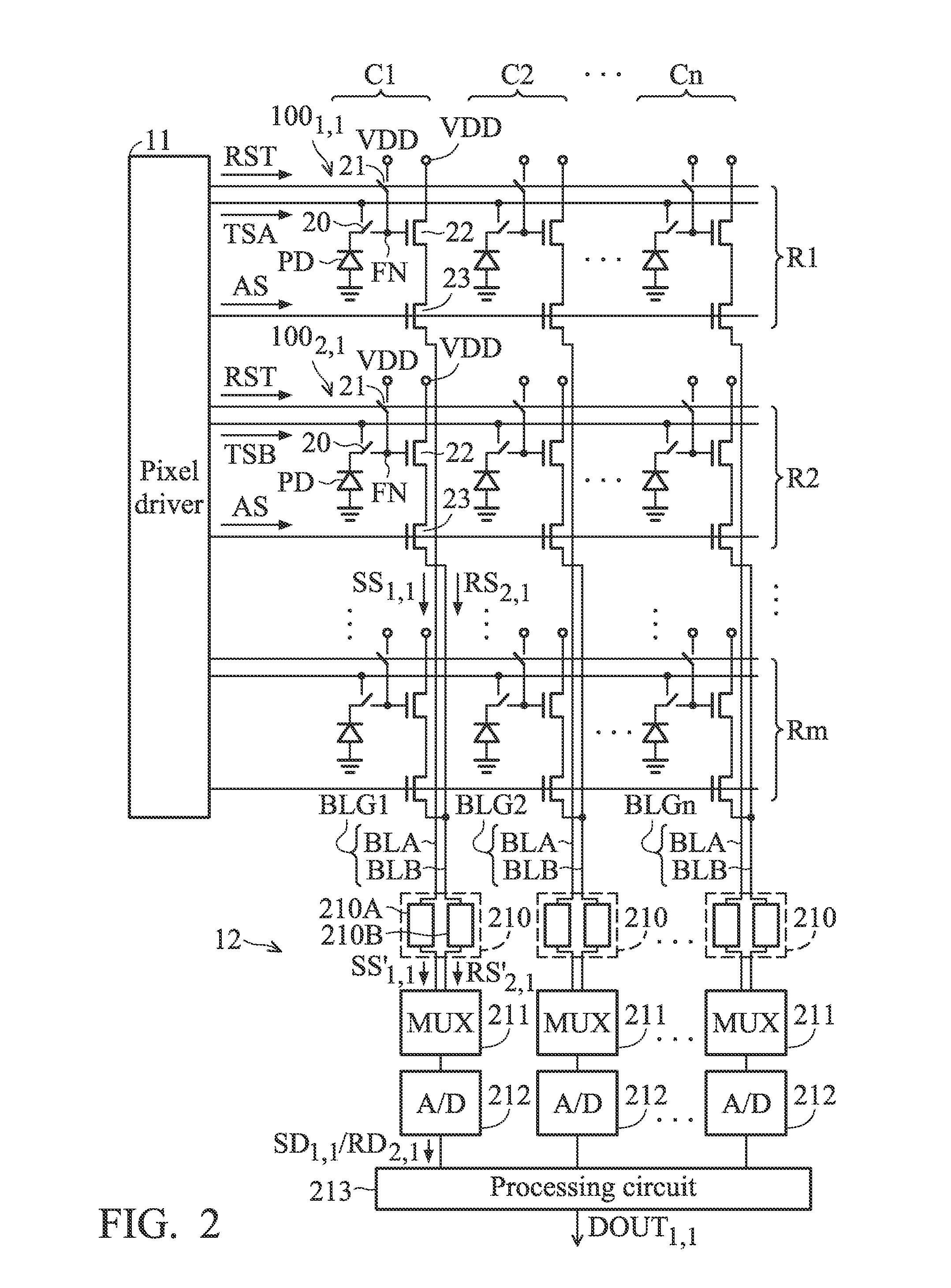
[0016]Sensing devices are provided. In an exemplary embodiment of a sensing device in FIG. 1, a sensing device 1 comprises a pixel array 10, a pixel driver 11, and a readout circuit 12. As shown in FIG. 1, there are a plurality of pixel groups 100 arranged in rows R1-Rm and column C1-Cn. In the embodiment, m is an even number. The pixel groups 100 are applied by a voltage source VDD. The pixel groups 100 arranged in the same column are coupled to the readout circuit 12 through one bit line group BLG. In the embodiment, each of the bit line groups BLG1-BLGn comprises two bit lines BLA and BLB. Among the pixel groups 100 arranged on the same column, some pixel groups 100...


PUM


Abstract

A sensing device is provided. The sensing device includes a plurality of pixel groups and a readout circuit. The pixel groups are arranged on a plurality of rows and a plurality of columns to form a pixel array. The pixel groups include a first pixel group and a second pixel group which are arranged on the different rows and the same column. The readout circuit is coupled to the pixel groups. When the first pixel group is triggered to perform a readout operation to generate a first sensing signal, the second pixel group performs a coupling operation to generate a reference signal. The readout circuit performs a subtraction operation based on the first sensing signal and the reference signal to generate a first readout data corresponding to the readout operation of the first pixel group.

Description

BACKGROUND OF THE INVENTION[0001]1. Field of the Invention[0002]The invention relates to a sensing device, and more particularly, to a sensing device with low power noise.[0003]2. Description of the Related Art[0004]Generally, power noise is a problem in COMS image sensors. Especially, when CMOS image sensors operate at low light conditions, the power noise may affect disadvantageously the sensing quality. Several manners have been provided to reduce the effect of the power noise. In one manner, a low pass filter is used to filter out noise from a power line. However, when an on-chip RC filter is used, high-frequency noise is not easily filtered out. Moreover, if an off-chip RC filter is used for a CMOS image sensor instead of on-chip RC filter, the off-chip RC filter will increases the cost of the COMOS image sensor. In another manner, a regulator is used to generate clear power with low noise. However, high-frequency noise is also not easily filtered out. Thus, the power may still...

Claims


Application Information

Patent Timeline
Patent Type & Authority Applications(United States)
IPC IPC(8): H04N5/378H04N5/376H04N5/369
CPCH04N5/378H04N5/3765H04N5/369H04N25/616H04N25/78H04N25/75
Inventor WANG, JIA-SHYANG
Owner HIMAX IMAGING LIMITED
Learn More