
Supply device for the supply of filled sacks to a palletizing device

a technology of supply device and palletizing device, which is applied in the direction of transportation and packaging, conveyor parts, stacking articles, etc., can solve the problems of amortization of the whole palletizing device and high cost effort, and achieve the effect of cost saving and increasing the speed of the palletizing devi

Active Publication Date: 2015-10-29
WINDMOELLER & HOELSCHER GMBH
View PDF27 Cites 8 Cited by
  • Summary
  • Abstract
  • Description
  • Claims
  • Application Information

AI Technical Summary

Benefits of technology

The present invention aims to increase the speed of Palletizing devices without increasing their cost. One way to achieve this is to refit existing palletizing devices with a new main supply belt and secondary feed belt. The secondary feed belt can be a smaller width as compared to the main supply belt, which reduces space requirement, weight, and complexity. The width of the secondary feed belt can be adapted based on the size of the filled sacks. The secondary feed belt can also be shifted beneath the main supply belt to further improve the speed of the palletizing process. Overall, the invention provides a cost-effective and simple solution to increase the speed of Palletizing devices.

Problems solved by technology

Like already apparent this leads to a temporal disadvantage since for the performance of a layer the conveyor belt has to insert the different rows in the sliding device one after the other.
These further leads to a higher cost effort since an amortization of the whole palletizing device occurs slower due to the slower palletizing speed.

Method used


Image

  • Supply device for the supply of filled sacks to a palletizing device
  • Supply device for the supply of filled sacks to a palletizing device
  • Supply device for the supply of filled sacks to a palletizing device

Examples


Embodiment Construction

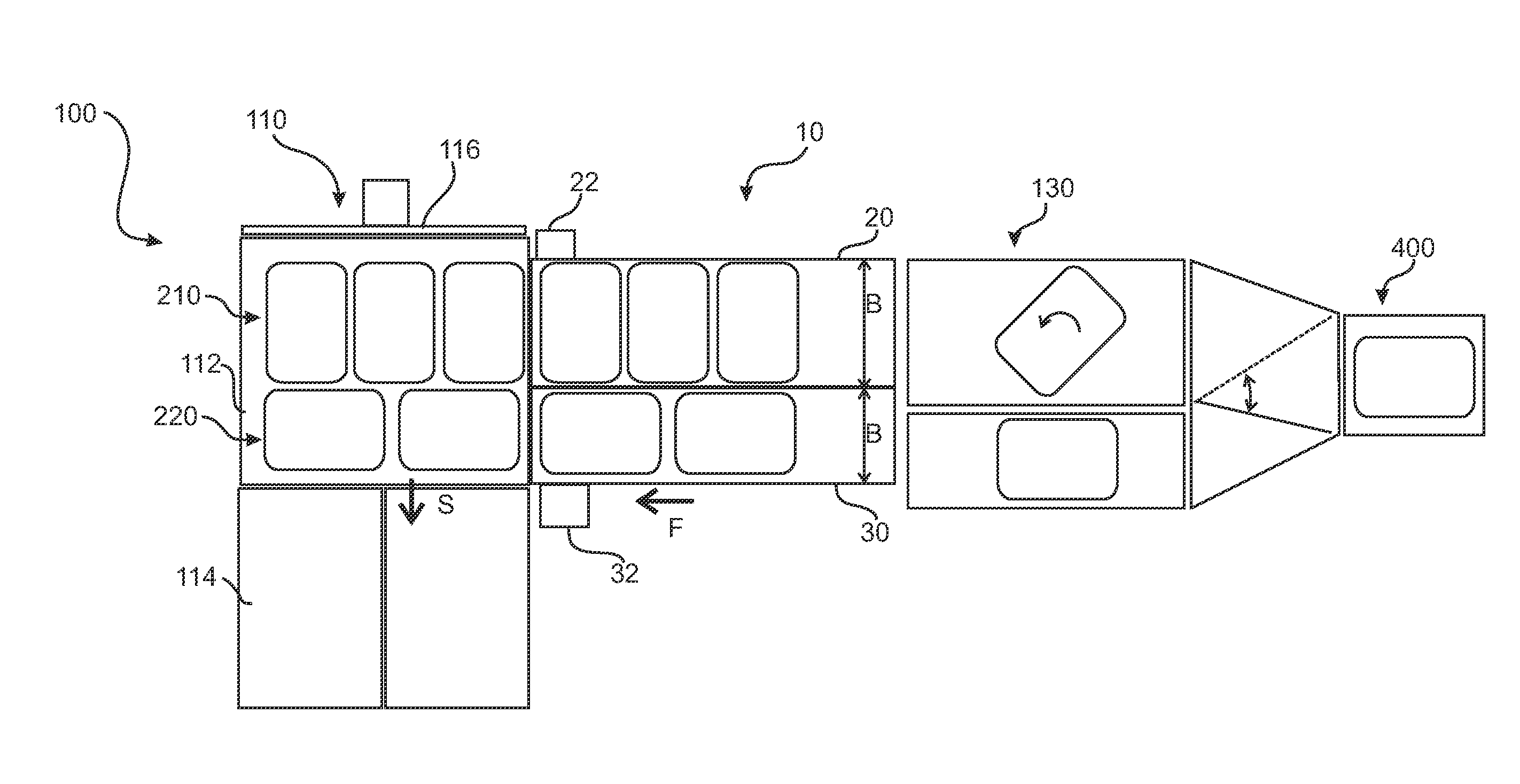
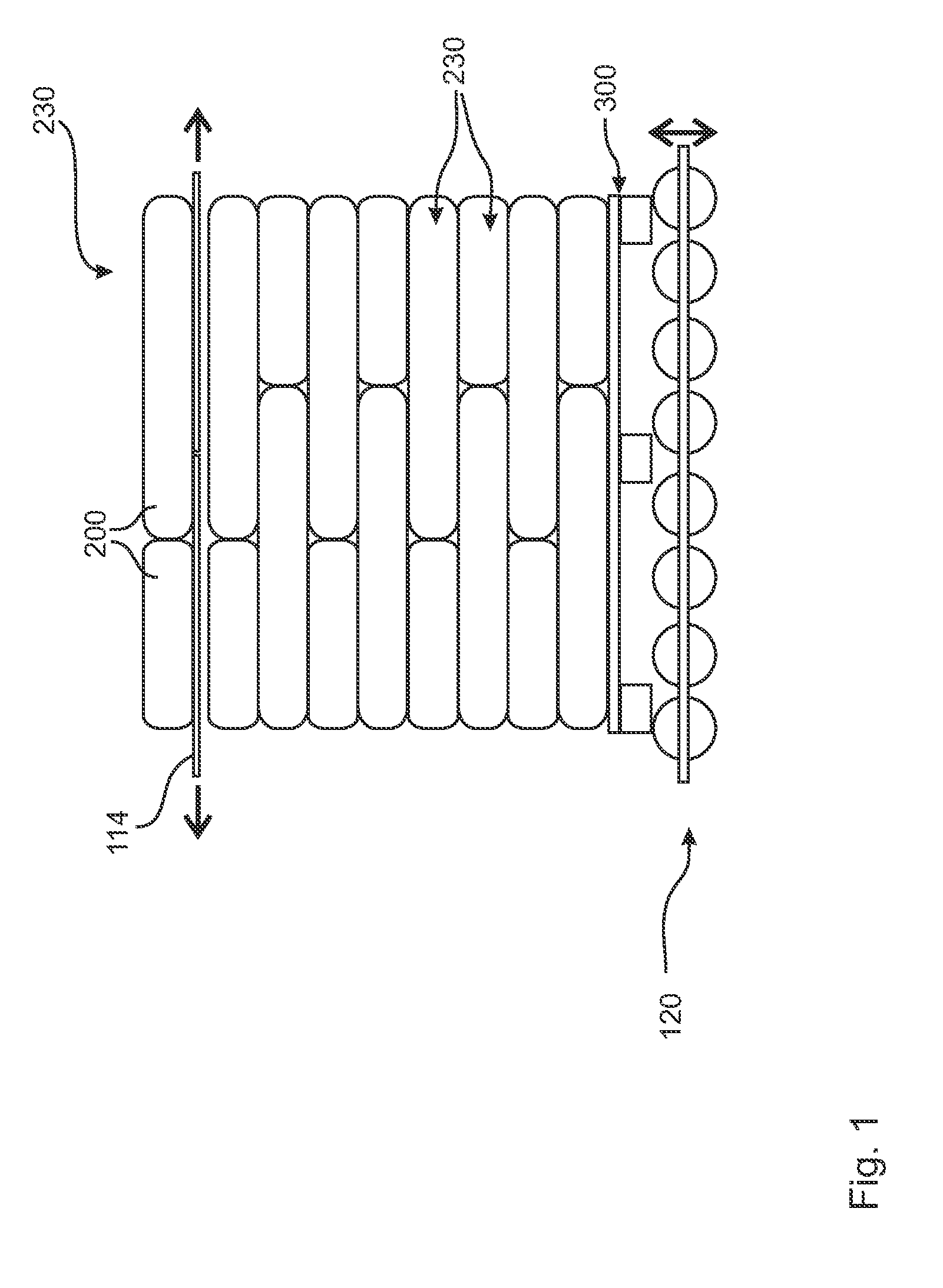
[0038]FIG. 1 schematically shows a lateral view how a sack stacking should be produced. This sack stacking comprises a plurality of different layers 230 which are here stacked to a sack stacking on a pallet 300. The pallet 300 is assembled on a lifting device 120 like shown with the double arrow and can be moved upwards and downwards. The drawing according to FIG. 1 shows an already progressed stacking process. The first layer is thereby processed in a way that the lifting device 120 is directly under the sliding table 114. At this time a layer 230 of filled sacks 200 is already assembled on the sliding table 114 like also shown in FIG. 1. If now the sliding table 114 opens the whole layer 230 falls a short distance to the lifting device 110 or to the there assembled pallet 300. Subsequently, the lifting device 120 is moved downwards with the palette 300 and with the layer 230 assembled on the pallet 300 so far that the sliding table 114 can reclose and take up the subsequent layer ...


PUM


Abstract

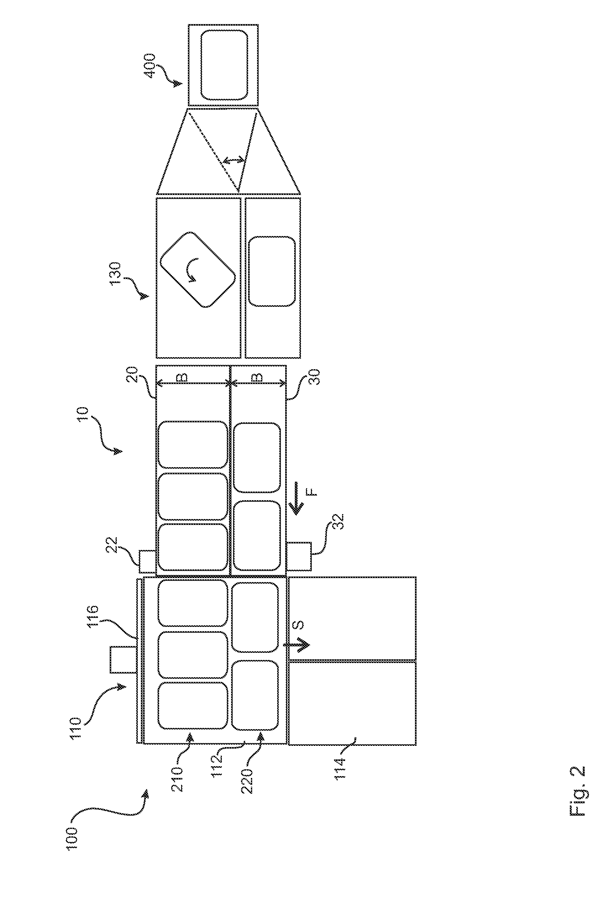
The invention relates to a supply device for the supply of filled sacks to a palletizing device, comprising a main supply belt for the supply of a first row of filled sacks on a sliding area of the palletizing device, wherein beneath the main supply belt at least one secondary feed belt is assembled for the supply of another row of filled sacks on the sliding area beneath a first row of filled sacks.

Description

RELATED APPLICATION[0001]This application claims the benefit of priority of German Patent Application No. 10 2014 105 932.8 filed Apr. 28, 2014, the contents of which are incorporated herein by reference in their entirety.DESCRIPTIONBackground of the Invention[0002]The present invention relates to a supply device for the supply of filled sacks to a palletizing device and a corresponding palletizing device.[0003]It is known that for a better transportation and a better handling filled sacks can be stacked to a sack stacking. Normally this occurs on a pallet or as a pallet-free sack stacking for the transportation of this sack stacking. Therefore, it is necessary to perform the sacks to rows and to layers wherein each layer later performs a layer of the sack stacking. Known palletizing devices comprise therefore normally sliding devices which comprise a sliding area for a layer performance. It is now crucial that the filled sacks can be supplied to a layer building sliding area. There...

Claims


Application Information

Patent Timeline
IPC IPC(8): B65G57/24B65G15/30B65G57/11B65G57/03B65G57/09
CPCB65G57/24B65G57/03B65G15/30B65G57/11B65G57/09B65G47/71B65G2201/0238
Inventor KOLKER, MARTINAHLERS, RALF
Owner WINDMOELLER & HOELSCHER GMBH
Learn More