Torsional Vibration Damping Arrangement For Said Powertrain Of A Vehicle

a technology of torsional vibration and damping arrangement, which is applied in the direction of fluid gearing, coupling, gearing, etc., can solve the problems of change in friction on the curved springs

Inactive Publication Date: 2015-10-29
ZF FRIEDRICHSHAFEN AG
View PDF1 Cites 10 Cited by
  • Summary
  • Abstract
  • Description
  • Claims
  • Application Information

AI Technical Summary

Benefits of technology

[0006]According to the invention, this object is met through a torsional vibration damping arrangement for the drivetrain of a vehicle, comprising an input region to be driven in rotation around an axis of rotation A and an output region, wherein there are provided between the input region and the output region a first torque transmission path and parallel thereto a second torque transmission path, and a coupling arrangement communicating with the output region for superposing the torques guided via the torque transmission paths, and wherein a phase shifter arrangement is provided in the first torque transmission path for generating a phase shift of rotational irregularities guided via the first torque transmission path relative to rotational irregularities guided via the second torque transmission path. The phase shifter arrangement is formed of at least one spring set comprising a curved spring. This spring set may also be referred to as an outer spring set. Often, an additional spring set is used in addition to the outer spring set or in place of the outer spring set. When the two spring sets are arranged radially, this additional spring set may also be referred to as inner spring set. These spring sets can be arranged so as to operate in parallel or in series. The inner spring set can also be constructed with a curved spring. By utilizing curved springs in the outer spring set and / or in the inner spring set, the total amount of spring energy that can be stored with the installation space remaining the same is increased in contrast to a construction with straight spring elements and sliding blocks disposed therebetween. Further, the use of curved springs allows a softer transition in a spring characteristic because sliding blocks can no longer come into collision with one another upon application of torque, since there are no longer any sliding blocks between individual short, straight coil springs. Acceleration peaks during a compression of the spring sets can be prevented in this way with advantageous results for the functioning of the phase shifter arrangement. Further, the use of a curved spring is economical because at least the sliding blocks are dispensed with. Curved springs can preferably be applied in the same configuration as that which is also already employed in dual mass flywheels.
[0007]A primary mass of the torsional vibration damping arrangement can be connected, e.g., to an output of a drive unit, formed in this case by a crankshaft, so as to be fixed with respect to rotation relative to it and to a control plate likewise so as to be fixed with respect to rotation relative to it. In this way, the primary mass also forms a planet gear carrier to which a stepped or non-stepped planet gear of the coupling arrangement is rotatably fastened by a planet gear bolt. Together with the planet gears, these components constitute a primary side of the torsional vibration damping arrangement. This fastening of the coupling arrangement to the primary mass is regarded as particularly advantageous in view of a stiff connection, accurate functioning, economical manufacture and a small number of parts.

Problems solved by technology

This can result in a change in friction on the curved springs.

Method used


Image

  • Torsional Vibration Damping Arrangement For Said Powertrain Of A Vehicle
  • Torsional Vibration Damping Arrangement For Said Powertrain Of A Vehicle
  • Torsional Vibration Damping Arrangement For Said Powertrain Of A Vehicle

Examples


Embodiment Construction

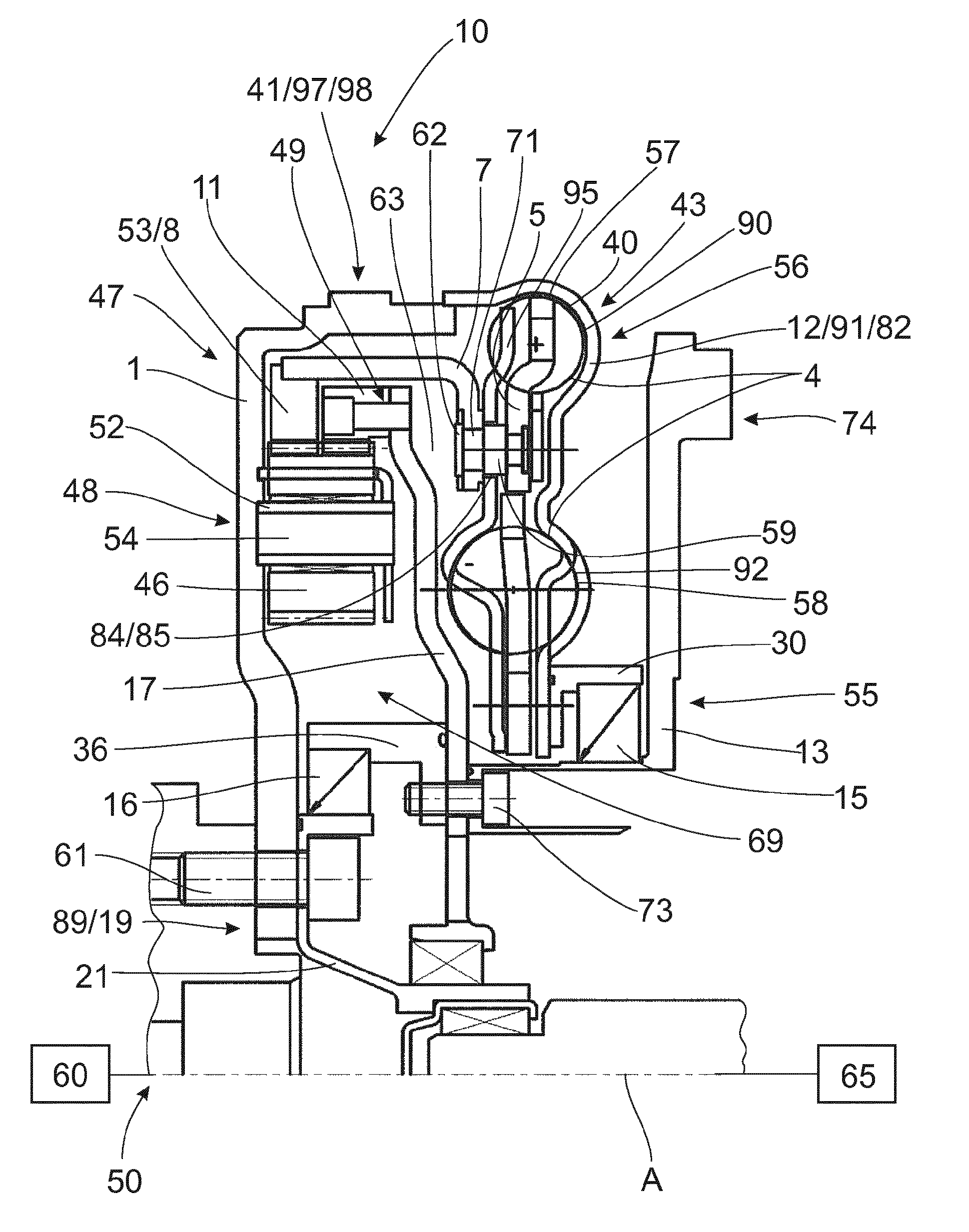
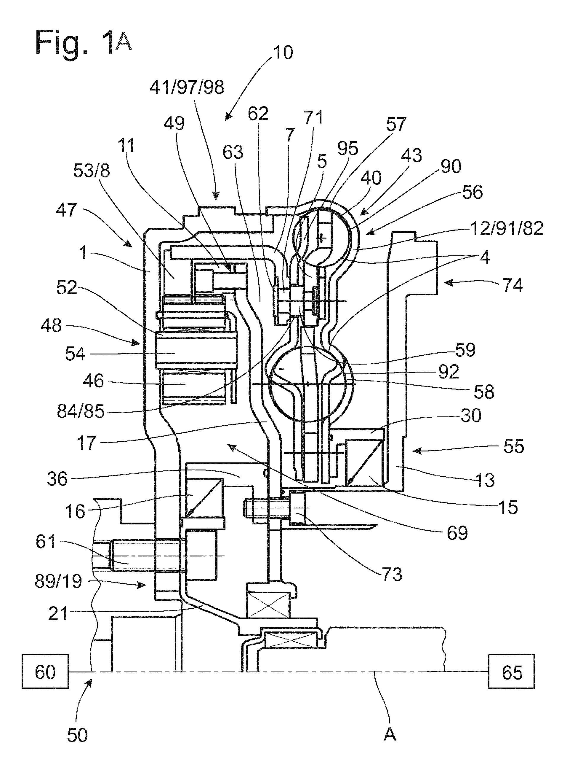
[0033]FIG. 1A shows a torsional vibration damping arrangement 10 which operates on the principle of power splitting or torque splitting. The torsional vibration damping arrangement 10 can be arranged in a drivetrain of a vehicle between a drive unit 60 and the subsequent portion of the drivetrain, i.e., for example, a start-up element 65 such as a friction clutch, a hydrodynamic torque converter, or the like.

[0034]The torsional vibration damping arrangement 10 comprises an input region, designated generally by 50. This input region 50 can be connected, for example by a screw connection 61, to an output of a drive unit 89 which is formed in this instance by a crankshaft 19. In the input region 50, the torque received from the drive unit 60 branches into a first torque transmission path 47 and a second torque transmission path 48. In the region of a coupling arrangement, designated generally by reference numeral 41, the torque components guided via the two torque transmission paths 47...


PUM


Abstract

A torsional vibration damping arrangement (10) for the drivetrain of a vehicle comprises an input region (50) to be driven in rotation around an axis of rotation A and an output region (55), and a first torque transmission path (47) and parallel thereto a second torque transmission path (48) which proceed from the input region, and a coupling arrangement (41) for superposing the torques guided via the two torque transmission paths, which coupling arrangement (41) communicates with the output region, and a phase shifter arrangement (43) for the first torque transmission path for generating a phase shift of rotational irregularities guided via the first torque transmission path relative to rotational irregularities guided via the second torque transmission path. The phase shifter arrangement comprises at least one spring set (40) with a curved spring (90).

Description

PRIORITY CLAIM[0001]This is a U.S. national stage of application No. PCT / EP2013 / 069740, filed on Sep. 23, 2014. Priority is claimed on the following application: Country: Germany, Application No.: 10 2012 218 729.4, Filed: Oct. 15, 2012, the content of which is incorporated herein by reference in its entirety.FIELD OF THE INVENTION[0002]The present invention is directed to a torsional vibration damping arrangement for the drivetrain of a vehicle, comprising an input region which is to be driven in rotation around an axis of rotation and an output region, wherein there are provided between the input region and the output region a first torque transmission path and parallel thereto a second torque transmission path and a coupling arrangement for superposing the torques guided via the torque transmission paths, wherein a phase shifter arrangement is provided in the first torque transmission path for generating a phase shift of rotational irregularities guided via the first torque trans...

Claims


Application Information

Patent Timeline
Patent Type & Authority Applications(United States)
IPC IPC(8): F16F15/131F16D3/66F16F15/134
CPCF16F15/13157F16D2300/06F16D3/66F16F15/13469F16F15/1478F16H2045/0268
Inventor LORENZ, DANIELCARLSON, CORAHOFFELNER, INGRIDHOCHE, TOBIAS
Owner ZF FRIEDRICHSHAFEN AG
Why Eureka
Try Eureka