Explosion-proof lamp cable gland

Inactive Publication Date: 2015-10-29
LI HONG SCI & TECH
View PDF4 Cites 8 Cited by
  • Summary
  • Abstract
  • Description
  • Claims
  • Application Information

AI Technical Summary

Benefits of technology

[0005]The primary object of the present invention is to provide an explosion-proof lamp cable gland that is simpler in structu

Problems solved by technology

Hence installation of the conventional explosion-proof lamps might require extra wiring or using the explosion-proof cable gland and the wiring box.
As a result, the produ

Method used


Image

  • Explosion-proof lamp cable gland
  • Explosion-proof lamp cable gland
  • Explosion-proof lamp cable gland

Examples


Embodiment Construction

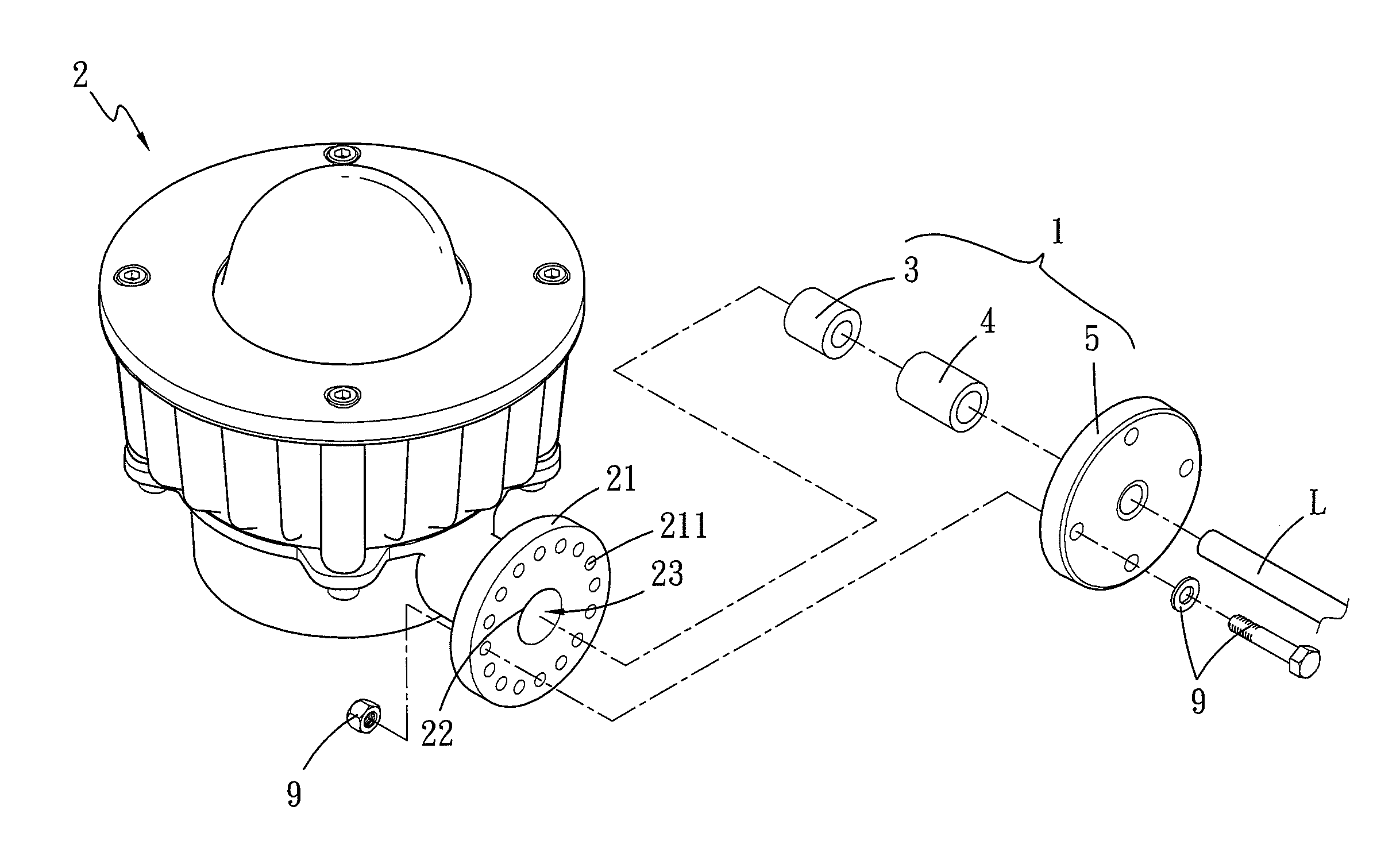
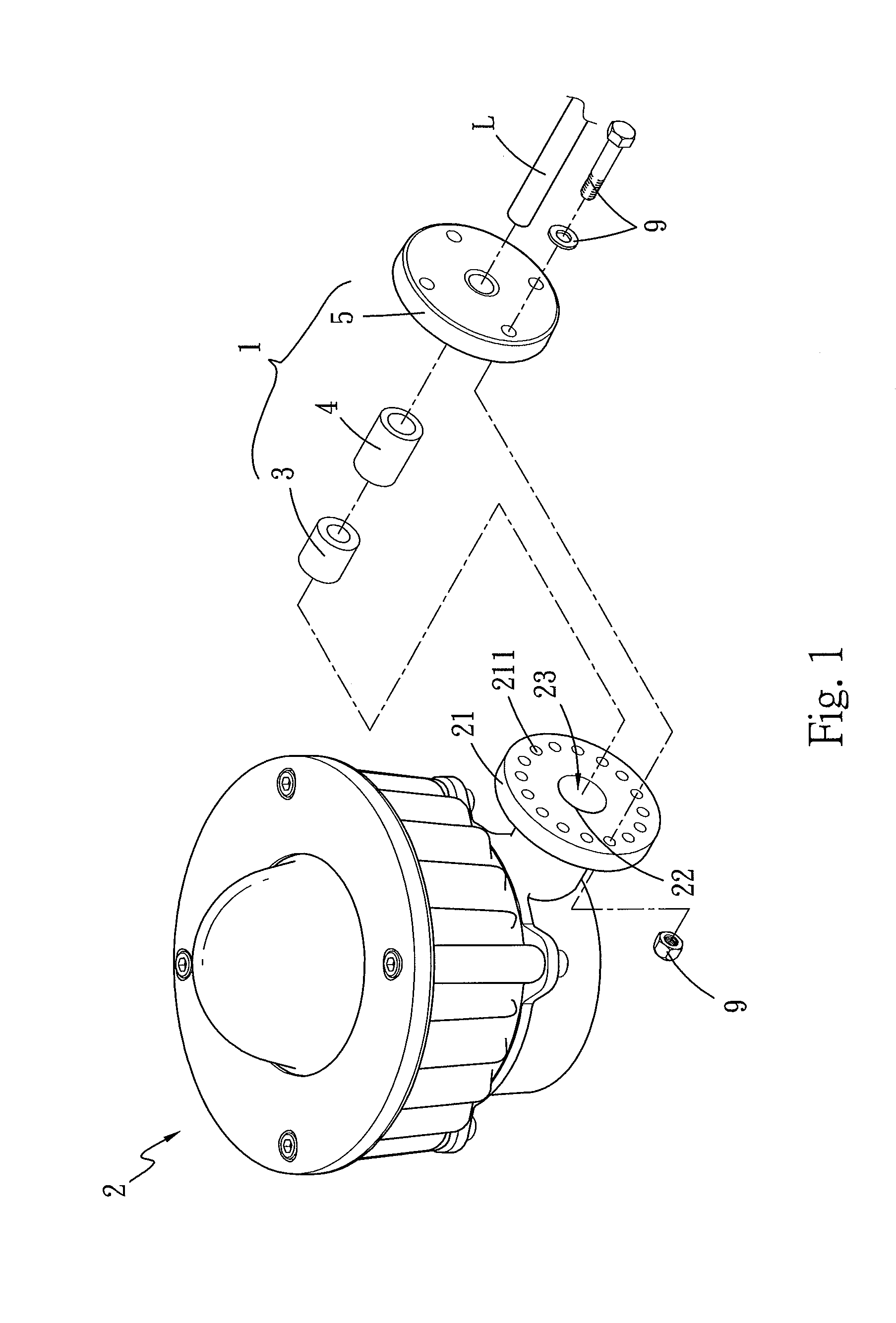
[0025]Varying types of embodiments are elaborated below to facilitate discussion of the invention. It is to be noted that same element in different embodiments is marked by the same numeral. Moreover, the explosion-proof lamp cable gland 1 of the invention is disposed in a channel 23 of a coupling portion 21 of an explosion-proof lamp 2 for a cable L to pass through (referring to FIG. 1). The coupling portion 21 of the explosion-proof lamp 2 further includes an opening 22 formed on the surface thereof to communicate the channel 23 and the outside. The coupling portion 21 can be used to couple serially with another explosion-proof lamp or mount directly or indirectly onto a wall. The cable L passes through the opening 22 and the channel 23 to connect to an electric control module disposed in the explosion-proof lamp 2.

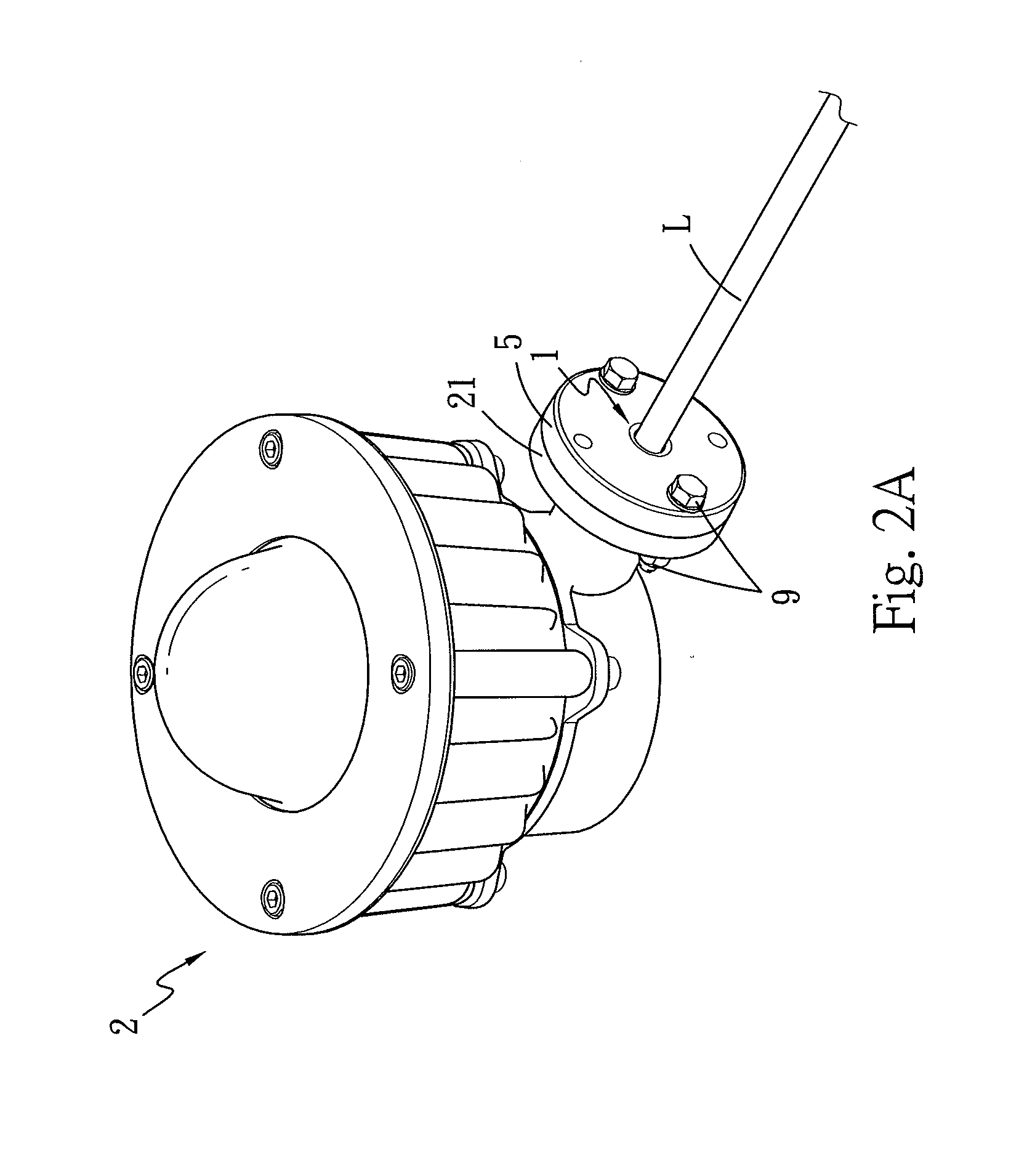
[0026]Please refer to FIGS. 1 through 2B for a first embodiment of the explosion-proof lamp cable gland 1 of the invention. The cable gland 1 includes a first explosion...


PUM


Abstract

An explosion-proof lamp cable gland is disposed in a channel of a coupling portion of an explosion-proof lamp for a cable to pass through, and includes a first explosion-proof member disposed at one end of the channel remote from an opening of the coupling portion and a compact member disposed at another end of the channel close to the opening of the coupling portion to connect to the first explosion-proof member. The explosion-proof lamp cable gland of the invention thus formed is simpler in structure and smaller in size, and can achieve explosion-proof effect as a conventional connector that is bulkier in size. Thus not only the cost is lower, but serial connection among the explosion-proof lamps also can be accomplished easily to make application versatile.

Description

FIELD OF THE INVENTION[0001]The present invention relates to an explosion-proof lamp cable gland and particularly to an explosion-proof lamp cable gland to facilitate serial connection and applications of explosion-proof lamps.BACKGROUND OF THE INVENTION[0002]Industrial locations such as chemical, petrochemical, oilfields, coalmines and the like often are scattered or stocked with gases, dust or chemicals that are inflammable, easily exploded or oxidized, or corrosive. Hence lamps used at those locations must be explosion-proof to avoid incidents of gas explosion or chemical explosion caused by sparks that might be generated by worn out or malfunctioned non explosion-proof lamps.[0003]The wiring of conventional explosion-proof lamps generally has to use an extra explosion-proof cable gland tightly compacting with the cable to enhance air tightness. When connecting one or more explosion-proof lamps in series, an additional explosion-proof wiring box is needed to wire and install the ...

Claims


Application Information

Patent Timeline
IPC IPC(8): F21V25/12F21V31/00H02G15/013F21V23/00
CPCF21V25/12H02G15/013F21V31/005F21V23/001
Inventor CHIEN, MING-TIENJUAN, CHING-YUANCHANG, HAN-WENJUAN, CHENG-LUNG
Owner LI HONG SCI & TECH
Why Eureka
Try Eureka