Deformation analysis device, deformation analysis method, and program

Active Publication Date: 2015-10-29
NIPPON STEEL CORP
View PDF3 Cites 4 Cited by
  • Summary
  • Abstract
  • Description
  • Claims
  • Application Information

AI Technical Summary

Benefits of technology

The invention reduces the rigidity of the element where a fracture has occurred by using a specific expression. This allows the element to behave more like an actual fracture after the fracture occurs.

Problems solved by technology

In the deformation of a material, for example, in press forming of a plate material, it has been known that a forming crack occurs in a formed product if a forming condition is not appropriate.
However, the conventional method determines whether or not the forming crack occurs, simply by referring to the forming limit diagram (proportional deformation FLD) in a case of what is called proportional deformation whose strain direction is always constant, and even if applied to actual press forming accompanied by complicated deformation, the method is not often able to find the appropriate forming condition.
In other words, the conventional method is greatly deformation path-dependent and is not applicable to a phenomenon such as a collision causing complicated deformation.
Therefore, if the size of the eliminated element is small, the stress applied to its surroundings is also small and a crack gradually progresses, but when the size of the eliminated element is large, the stress applied to elements therearound is large and a crack in the simulation is likely to progress more than actually.
Therefore, in the conventional method, it is sometimes difficult to predict a behavior after the occurrence of the fracture.
However, Patent Literature 3 does not disclose a concrete way of setting the correction characteristic.

Method used


Image

  • Deformation analysis device, deformation analysis method, and program
  • Deformation analysis device, deformation analysis method, and program
  • Deformation analysis device, deformation analysis method, and program

Examples


Embodiment Construction

[0057]Hereinafter, modes for carrying out the present invention will be described with reference to the attached drawings.

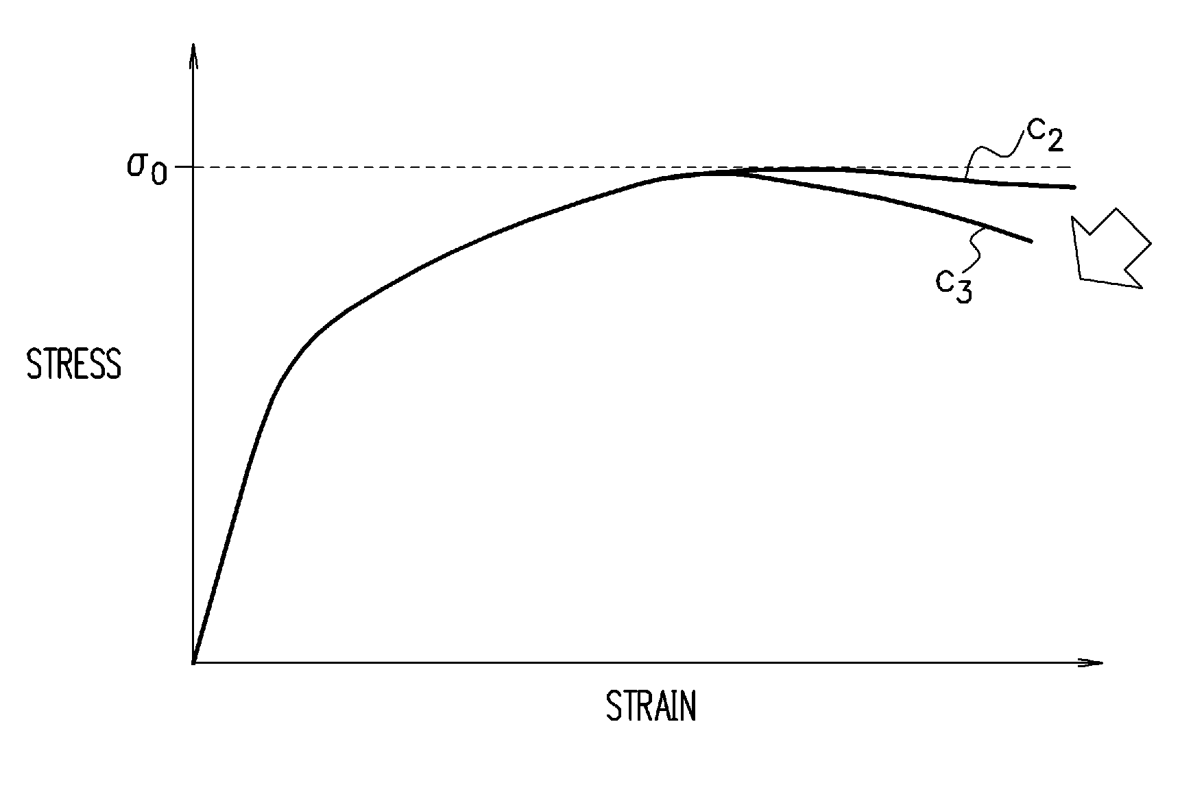
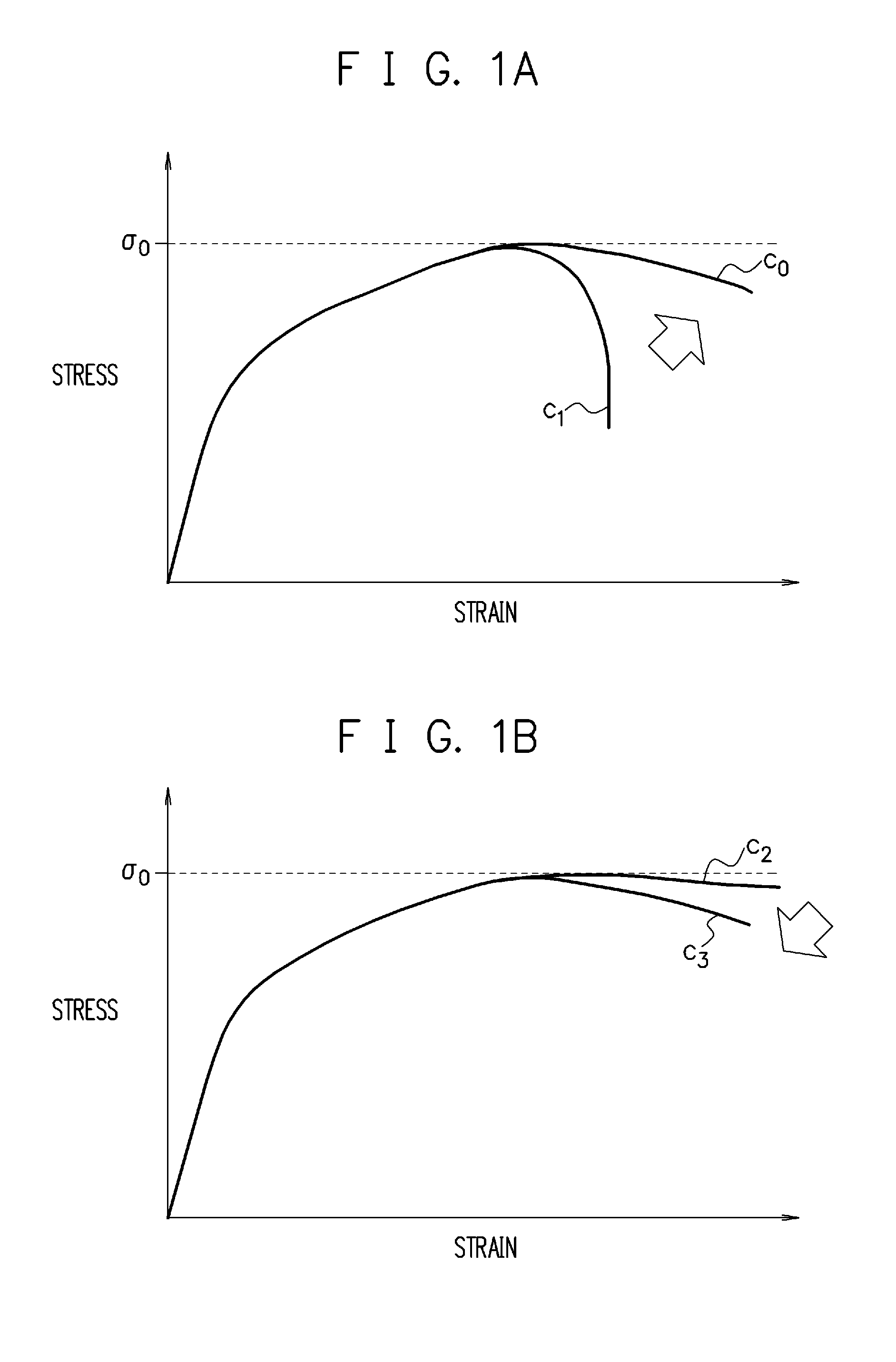
[0058]In this embodiment, a deformation analysis of a material is performed by using FEM (Finite Element Method). Further, fracture determination is performed based on a stress FLD. When a fracture occurs in a certain element (actually, a certain evaluation point that the element has), the element is not eliminated at once but rigidity of the element is gradually decreased, and at a point in time at which the rigidity is decreased to some degree, the element is eliminated. The rigidity decrease of the element is expressed by manipulating a stress applied to the element. Concretely, it is expressed by the following expression based on the concept of continuum damage mechanics.

σ=(1−D)σ′  (expression 1)

[0059]Here, σ is a stress with the rigidity decrease taken into consideration, D is a damage variable (note that 0≦D≦1) in the continuum damage mechanics, and σ′ is a...


PUM


Abstract

The deformation analysis device includes: a storage unit (12) which stores analysis data of a material; a state variable calculating unit (152) which calculates stresses and other state variables of respective elements of the material at each point in time of deformation of the material, based on the analysis data; a fracture determining unit (153) which, based on the calculated state variables, determines whether or not a fracture has occurred in each of the elements of the material, based on a fracture limit stress curve which is found in advance for the material; and a stress correcting unit (154) which, regarding an element in which it is determined that the fracture has occurred, out of the elements of the material, reduces σ by the following expression σ=(1−D)σ′ where σ is a stress with a rigidity decrease taken into consideration, D is a damage variable (note that 0≦D≦1) in continuum damage mechanics, and σ′ is a stress with the rigidity decrease not taken into consideration, to thereby decrease rigidity of the relevant element, without eliminating the element, and updates the analysis data.

Description

TECHNICAL FIELD[0001]The present invention relates to a deformation analysis device, a deformation analysis method, and a program.BACKGROUND ART[0002]In the deformation of a material, for example, in press forming of a plate material, it has been known that a forming crack occurs in a formed product if a forming condition is not appropriate. Therefore, there has been used a method in which, by using a computer, the press forming of the plate material is simulated under various forming conditions and validity of the forming conditions is determined based on the result (for example, Patent Literature 1).[0003]In general, such a method repeatedly executes the following three steps until an appropriate forming condition under which no forming crack occurs and also other requirements (for example, weight reduction, thinning, and so on of a product) are satisfied is obtained:[0004](1) The press forming is simulated under a set forming condition and strains of portions of a material are su...

Claims


Application Information

Patent Timeline
IPC IPC(8): G06F17/50G06F17/10
CPCG06F17/10G06F17/5009G01N2203/006G01N2203/0246G01N2203/0067G01N2203/0218G06F30/23G06F2111/10G06F30/20G06F2119/14
Inventor HIROSE, SATOSHINIWA, TOSHIYUKITSUNEMI, YUSUKE
Owner NIPPON STEEL CORP
Why Eureka
Try Eureka