Smart screening barrier and system

a technology of smart screening and barrier, applied in the field of security barriers, can solve the problems of prior art terrorist uncovering schemes, short individual handling capacity, hidden dangerous objects, etc., and achieve the effect of reducing the likelihood of false alarms and mitigateing a potential explosion or other act of terrorism

Active Publication Date: 2015-10-29
APSTEC SYST USA
View PDF1 Cites 5 Cited by
  • Summary
  • Abstract
  • Description
  • Claims
  • Application Information

AI Technical Summary

Benefits of technology

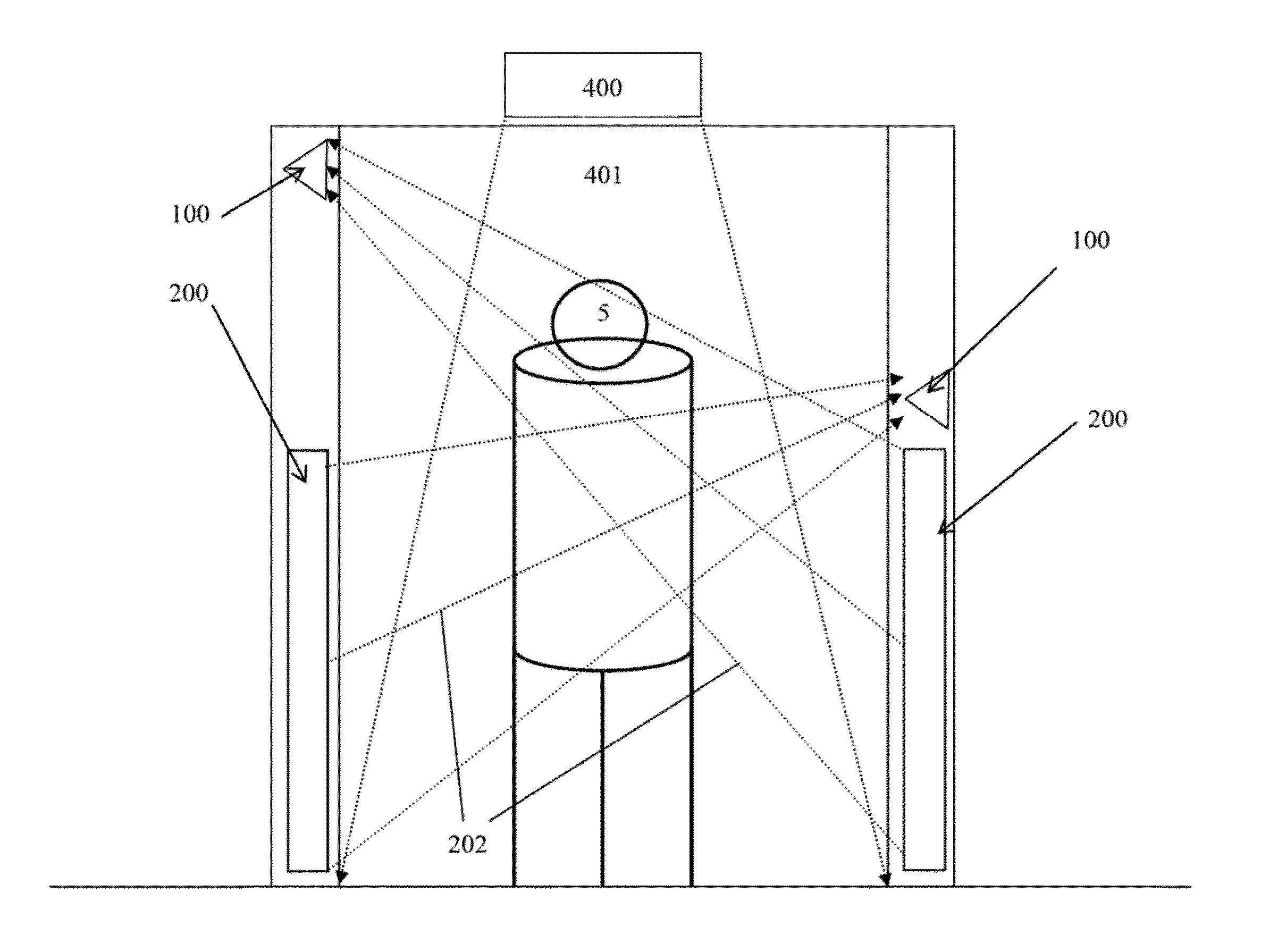
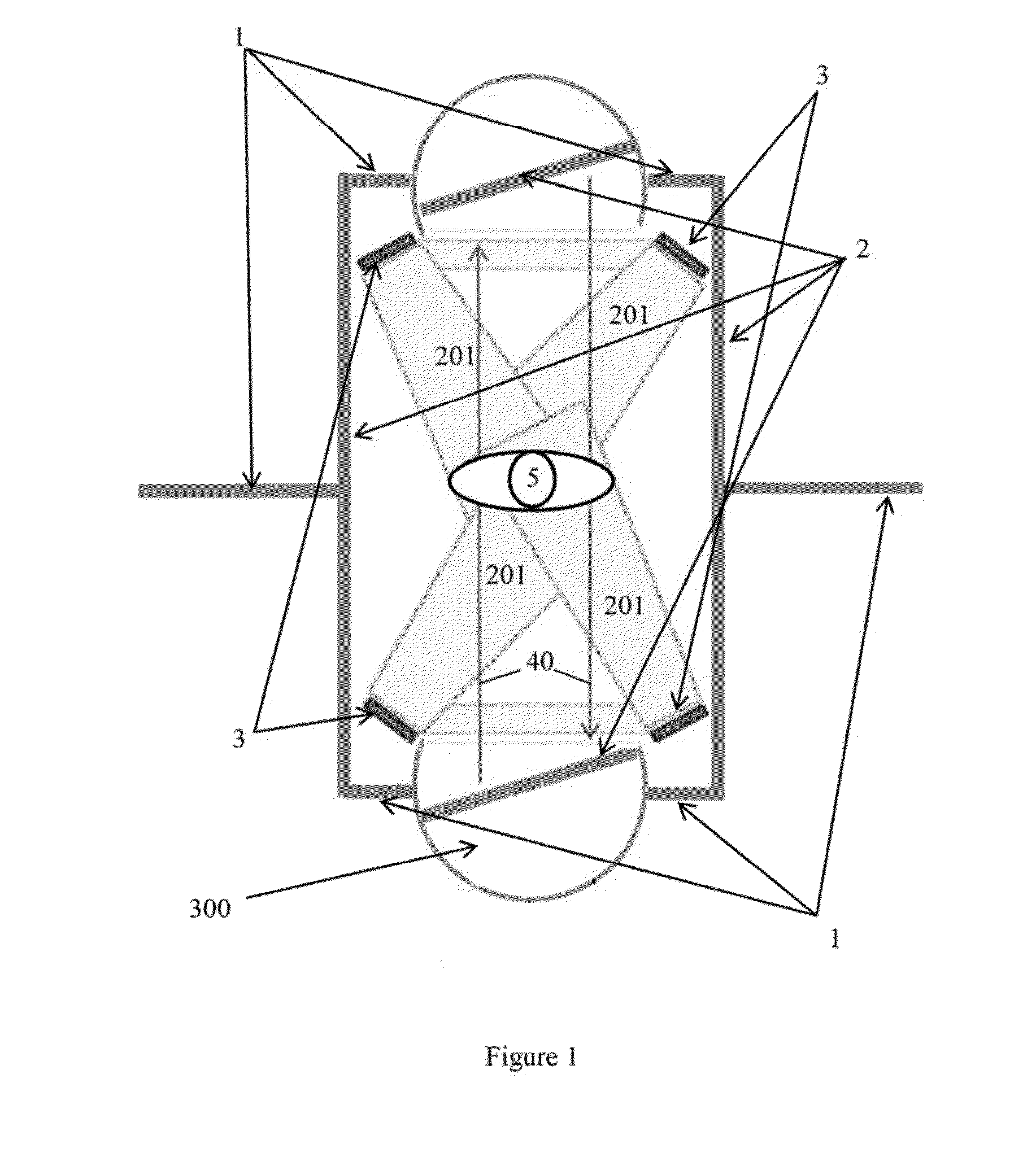
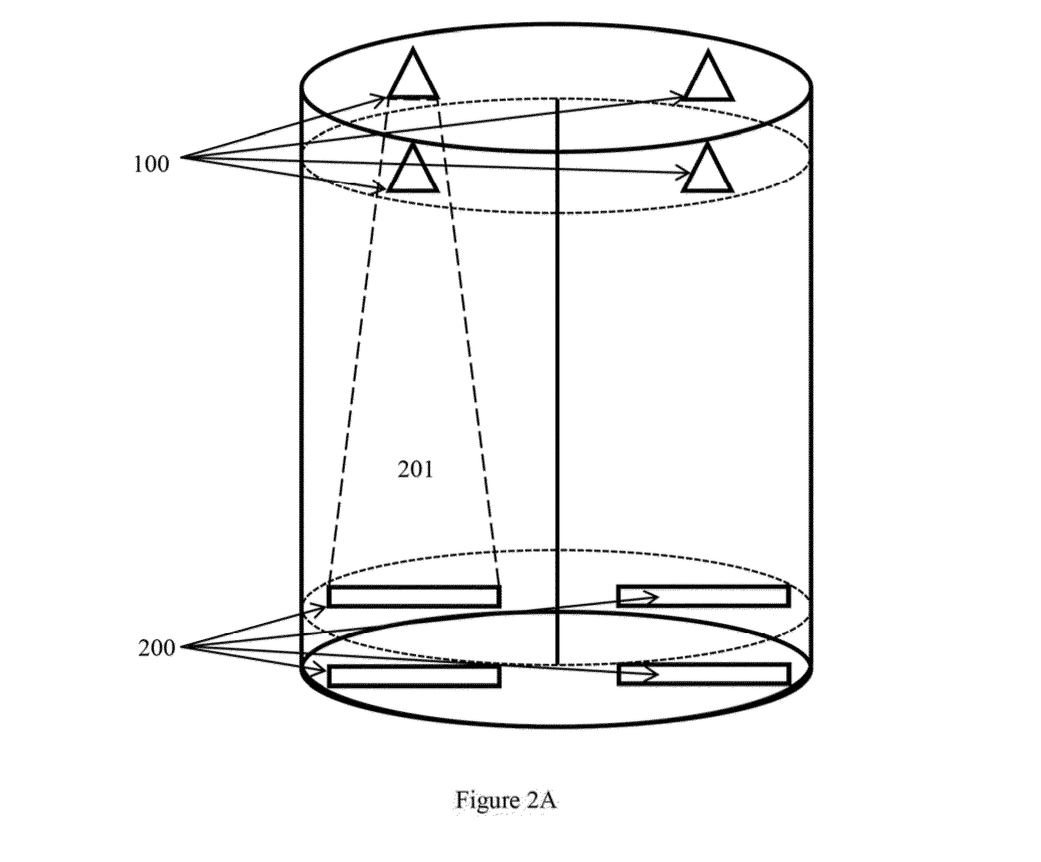
[0007]The present invention claims a security barrier and system for the screening of individuals, e.g., for application in areas with high traffic flows. The invention comprises at least two revolving door mechanisms, or alternatively, automatic doors, used as entrance and exit points to / from an isolated area located between the doors. The doors, as well as the walls and surrounding structures of the isolated area, are made of blast-resisting glass and / or concrete, in order to mitigate a potential explosion or other act of terrorism. Screening mechanisms are employed in the isolated area as well as within the entrance and exit points. More screening devices / mechanisms lower the likelihood of false alarms and allow for further confirmation of suspected individuals. Various means for screening can be used including, but not limited to, metal detection, microwave imaging, video imaging, and infrared imaging. An alarm can be triggered if a signal from any of the screening mechanisms exceeds a pre-determined threshold value. Alternatively, a silent alarm can be triggered in a similar fashion, in order to alert and obtain first responders before alarming an individual carrying a potential explosive.

Problems solved by technology

Both inventions are a kind of automatic detection device, but are short in their capability of dealing with an individual who might be wearing or carrying a hidden dangerous object.
Prior art terrorist uncovering schemes, including but not limited to those mentioned above, are dangerous, since a terrorist most often detonates when realizing he has been caught in order to injure as many bystanders as possible.
Security personnel who must approach a potential suicide bomber stand a very high risk, which also potentially impairs effectiveness of the security approach.

Method used


Image

  • Smart screening barrier and system
  • Smart screening barrier and system
  • Smart screening barrier and system

Examples


Embodiment Construction

Definitions

[0013]“Means for detection,” as used herein, refer to various means for screening / detection which are applicable with the presently claimed system including, but not limited to, metal detection, microwave detection, video detection, microwave-video imaging, infrared detection, electromagnetic imaging, x-ray imaging, ultrasonic imaging, ultrasound imaging, and other known methods. Methods of detection disclosed by the following patents are incorporated herein fully by reference and exemplify, without limiting, alternate means of detection compatible with the present invention: U.S. Pat. No. 8,159,534, to Kuznetsov et al., U.S. Pat. No. 8,228,374, to Kuznetsov et al., U.S. Pat. No. 6,791,487, to Singh et al., U.S. Pat. No. 6,469,624, to Whan et al., U.S. Pat. No. 5,600,303, to Husseiny et al, and PCT / US Patent Application No. PCT2013 / 027932, filed by Bergen et al.

[0014]“Microwave (MW) imaging,” as used herein for the means of detection, can be achieved using various techniq...


PUM


Abstract

A barrier and system for the protection of a crowd from terrorists, by evaluating each individual for any concealed prohibited items. Each individual is exposed to one or more screening mechanisms, controlled by a monitoring unit, while passing in an organized fashion through an enclosed walkway containing the screening mechanism, and exiting on the other side. When a prohibited object is detected, response is provided and the smart door device is locked to detain and isolate the suspected individual in the device structure's interior. The structure of the invention is also configured to deflect the blast created by a potential explosion and prevent harm to other individuals and structures nearby.

Description

CROSS-REFERENCE TO RELATED APPLICATIONS[0001]This patent application claims priority to, and incorporates fully by reference, U.S. Provisional Patent Application No. 61 / 945,921, filed Feb. 28, 2014.FIELD OF THE INVENTION[0002]This invention relates to a security barrier for the controlled transit of people, animals, and carried items, particularly for tourist attraction areas, high-capacity and high-flow areas, and mass transit areas such as train stations and airports.BACKGROUND OF THE INVENTION[0003]U.S. Patent Application No. 2003 / 0136052, by De Boer, discloses a revolving door, comprising a rotatable partition embodied such that in, at, or on the partition, one or more means for the detection of inadmissible goods is provided. U.S. Pat. No. 6,742,301, to Schwarz, also discloses a revolving door, but with a metal detection function. Both inventions are a kind of automatic detection device, but are short in their capability of dealing with an individual who might be wearing or car...

Claims


Application Information

Patent Timeline
Patent Type & Authority Applications(United States)
IPC IPC(8): G08B13/22G07C9/00G08B13/196
CPCG08B13/22G07C9/00126G08B13/19634G08B15/007E05G5/003E06B3/90
Inventor KELLERMANN, DAVID GUSTAVKUZNETSOV, ANDREYGORSHKOV, IGOR
Owner APSTEC SYST USA
Why Eureka
Try Eureka