Image projection apparatus and light source unit
a technology of image projection and light source, which is applied in the direction of optics, coupling device connection, instruments, etc., can solve the problems of difficult engagement work of connectors and difficult replacement work of lamp units
- Summary
- Abstract
- Description
- Claims
- Application Information
AI Technical Summary
Benefits of technology
Problems solved by technology
Method used
Image
Examples
first example embodiment
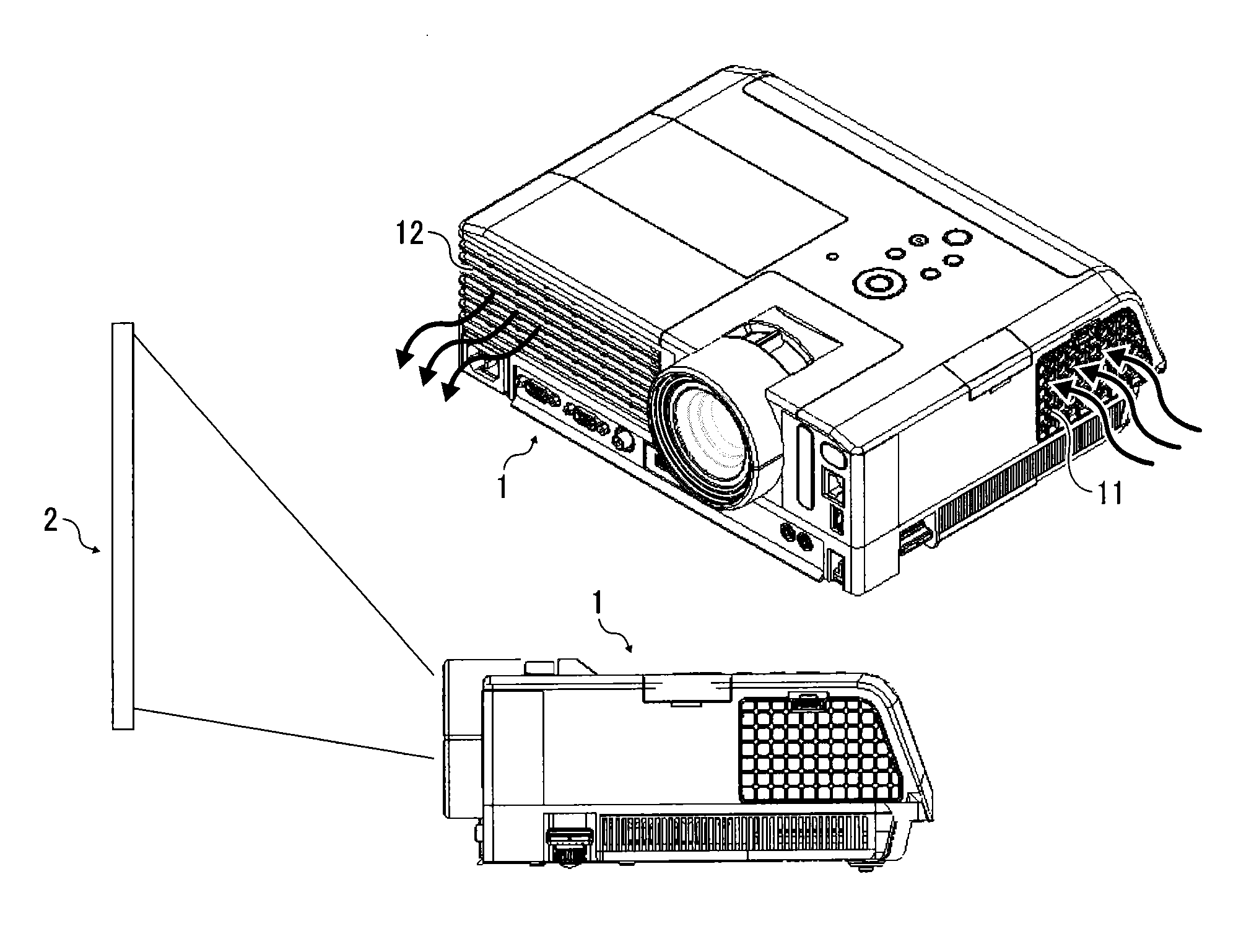
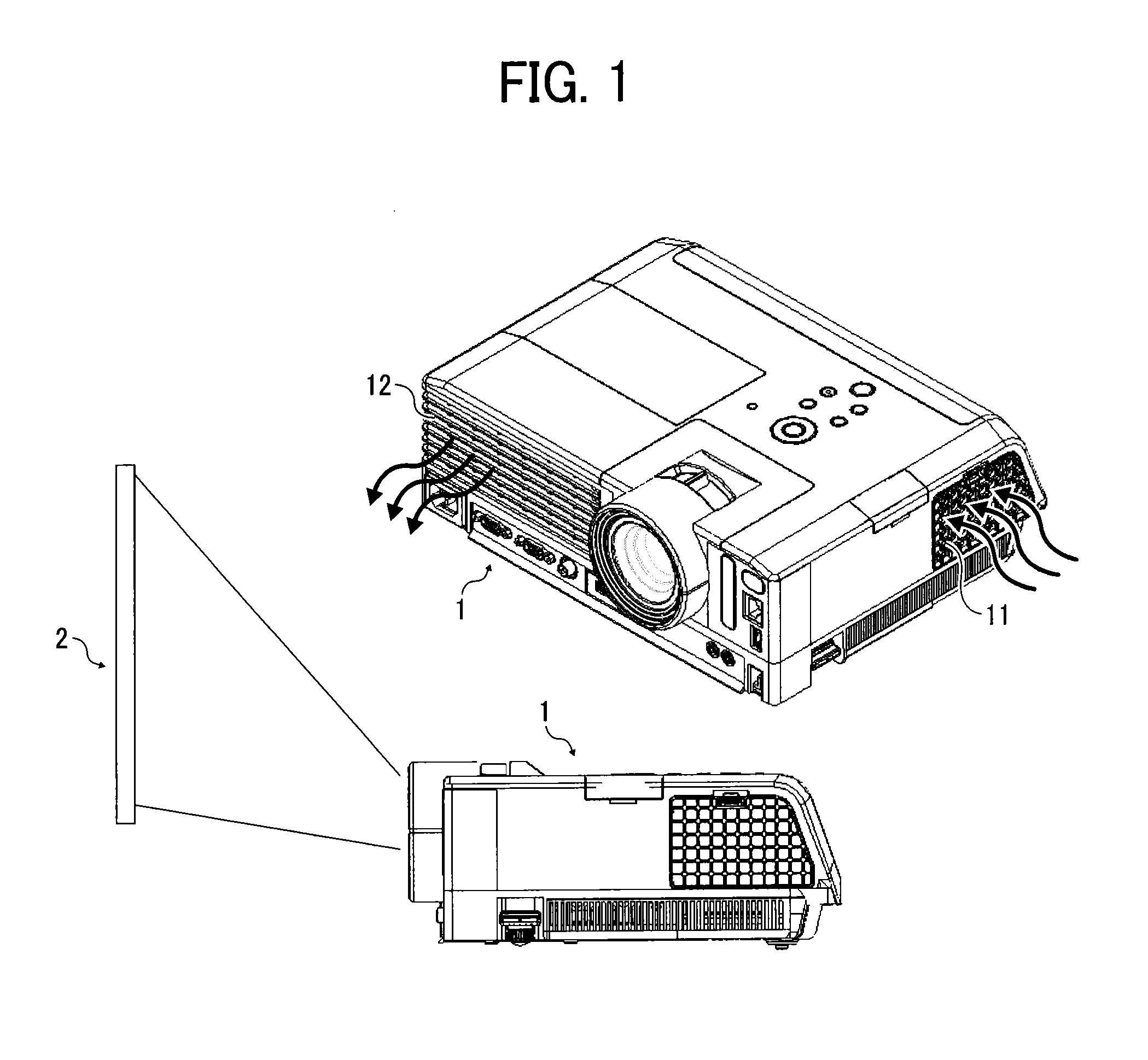
[0030]A description is given of an image projection apparatus 1 according to a first example embodiment with reference to drawings. FIG. 1 is a perspective view of the image projection apparatus 1, and a side view of the image projection apparatus 1 that can project an image onto a screen 2.
[0031]The image projection apparatus 1 generates images based on image data input from other apparatuses such as a personal computer (PC) and video camera, and projects the generated images on the screen 2 or the like. The image projection apparatus 1 is available as liquid crystal projectors, which have been enhancing resolution of liquid crystal panel, enhancing luminance of light source by improving efficiency, and lowering market prices. Further, the image projection apparatus 1 is available as light-weight compact projectors employing a digital micro-mirror device (DMD). These projectors are used at offices, schools, homes, and others. For example, front type projectors, which enhance portab...
second example embodiment
[0047]FIG. 14 illustrates a configuration for engaging the input terminal 24 and the output terminal 34 according to a second example embodiment, in which leaf springs 51 a and 52a having a warped or curved shape are used. In this configuration, each of the leaf springs 51a and 52a can deform along the connection direction or engagement direction of the input terminal 24 and the output terminal 34 (e.g., upper-lower direction in FIG. 14), and further in the horizontal direction, which is substantially perpendicular to the connection direction or engagement direction. Therefore, even if a length of the input terminal 24 and the output terminal 34 in the connection direction or engagement direction is short, each of the leaf springs51 a and 52a has a shape that does not interfere the engagement of the input terminal 24 and the output terminal 34.
[0048]Further, as to the above described first and second example embodiments, the supporter (e.g., leaf spring) having the guide is disposed...
example embodiments
Effect of Example Embodiments
[0049]As to the above described first and second example embodiments, the connectors used for power-supply to the light source unit are disposed moveably in a given moveable range so that the connectors do not interfere the positioning of the light source unit and the optical engine, and the guide is disposed at an end of at least one of the connectors to guide one engagement member to another engagement member at a desired position when engaging the connectors, and the supporter can be used to regulate the moveable range of the connector.
[0050]By disposing the guide at an end of at least one of the connectors used for power-supply to the light source unit, the inclining of the connector can be prevented, and one engagement member disposed at an end of one connector can be guided to a desired engagement position with another engagement member disposed at an end of another connector, with which the connectors can be engaged smoothly. Therefore, the connec...
PUM
 Abstract
Description
Claims
Application Information
 - R&D
- Intellectual Property
- Life Sciences
- Materials
- Tech Scout
- Unparalleled Data Quality
- Higher Quality Content
- 60% Fewer Hallucinations
Browse by: Latest US Patents, China's latest patents, Technical Efficacy Thesaurus, Application Domain, Technology Topic, Popular Technical Reports.
© 2025 PatSnap. All rights reserved.Legal|Privacy policy|Modern Slavery Act Transparency Statement|Sitemap|About US| Contact US: help@patsnap.com


