Zoom lens and image pickup apparatus including the same

a technology of zoom lens and image pickup, which is applied in the field of zoom lens, can solve the problems of difficult downsizing of entire zoom lens, difficult suppression, and noise in operation affecting photography, and achieves the effect of small size and weight, high magnification

Active Publication Date: 2015-11-05
CANON KK
View PDF1 Cites 13 Cited by
  • Summary
  • Abstract
  • Description
  • Claims
  • Application Information

AI Technical Summary

Benefits of technology

[0009]It is an object of the present invention to provide a zoom lens in which a paraxial refractive power arrangement of a first lens unit and a zoom lens unit is appropriately defined, which has a high magnification and is usable in a super telephoto range (for example, a high magnification of 7× or more and a half angle of field of 3 degrees or less at a telephoto end), and which is small in size and weight even in a case of adapting to a large sensor (for example, one inch or more).
[0012]According to the one embodiment of the present invention, it is possible to achieve the zoom lens which has the high magnification and is usable in the super telephoto range (for example, the high magnification of 7× or more and the half angle of field of 3 degrees or less at the telephoto end), and which is small in size and weight even in the case of adapting to the large sensor (for example, one inch or more).

Problems solved by technology

With a zoom lens for photographing a moving image, a zoom operation or a focus operation is performed during photographing, and hence in a case where a total lens length is changed at the time of the operation, an operation sound becomes noise to affect the photography, which is undesirable.
In regard to the zoom lens described in Japanese Patent Application Laid-Open No. 2007-139858, as a problem in adapting to a still larger image pickup element and increasing a magnification while maintaining a large aperture ratio, an effective diameter on an image side of a zoom lens unit is increased, and hence the entire zoom lens is difficult to downsize.
In regard to the zoom lens described in Japanese Patent Application Laid-Open No. 2004-085846, as a problem in further increasing the magnification, a movement amount of a third lens unit for correcting an image plane is difficult to suppress, and in addition, a total lens thickness of a first lens unit is large, with the result that the entire zoom lens is difficult to downsize.

Method used


Image

  • Zoom lens and image pickup apparatus including the same
  • Zoom lens and image pickup apparatus including the same
  • Zoom lens and image pickup apparatus including the same

Examples


embodiment 1

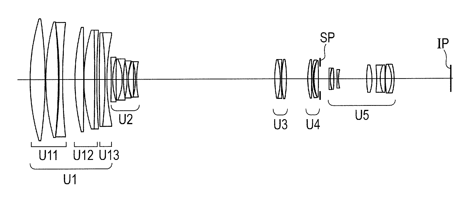
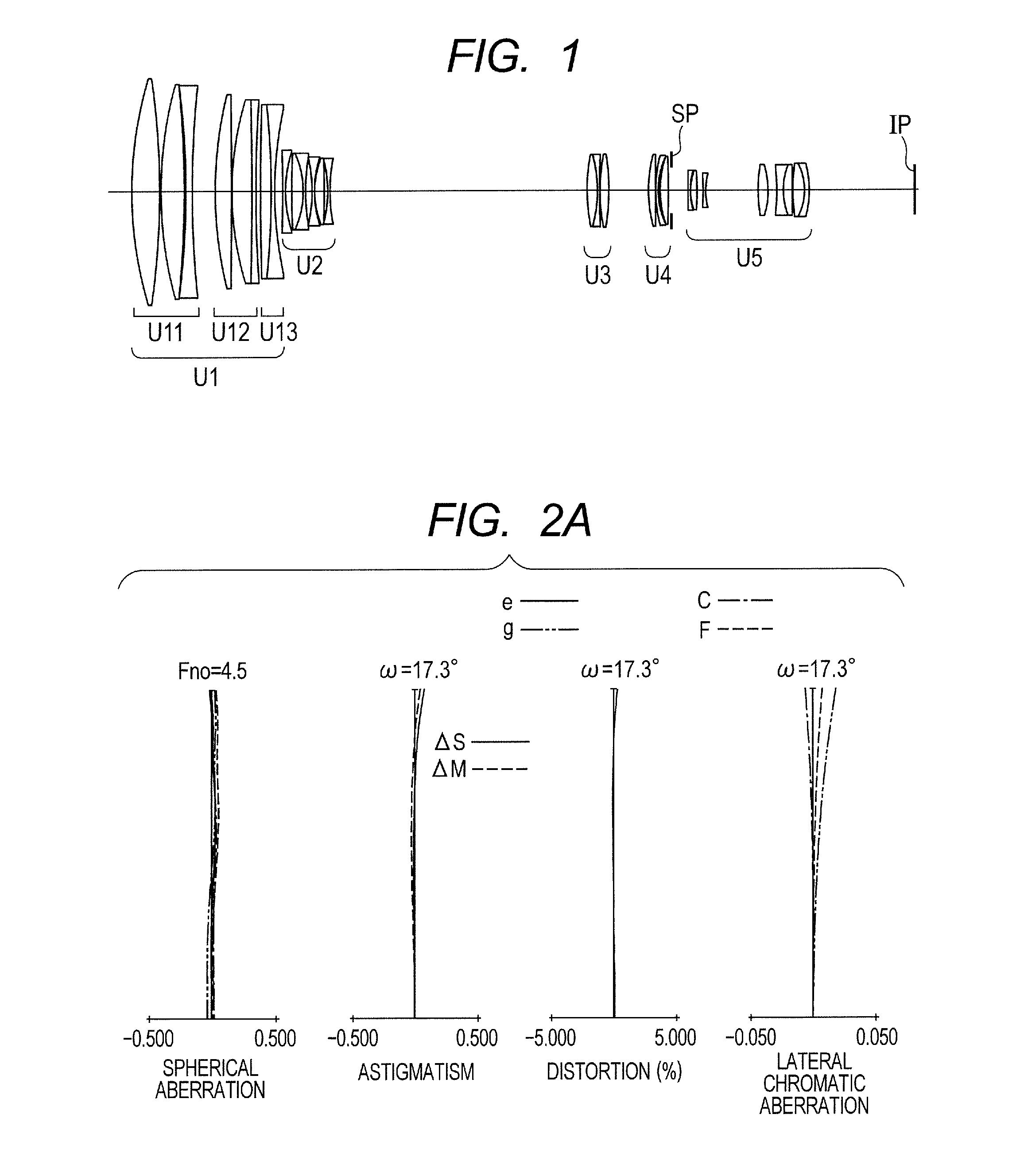
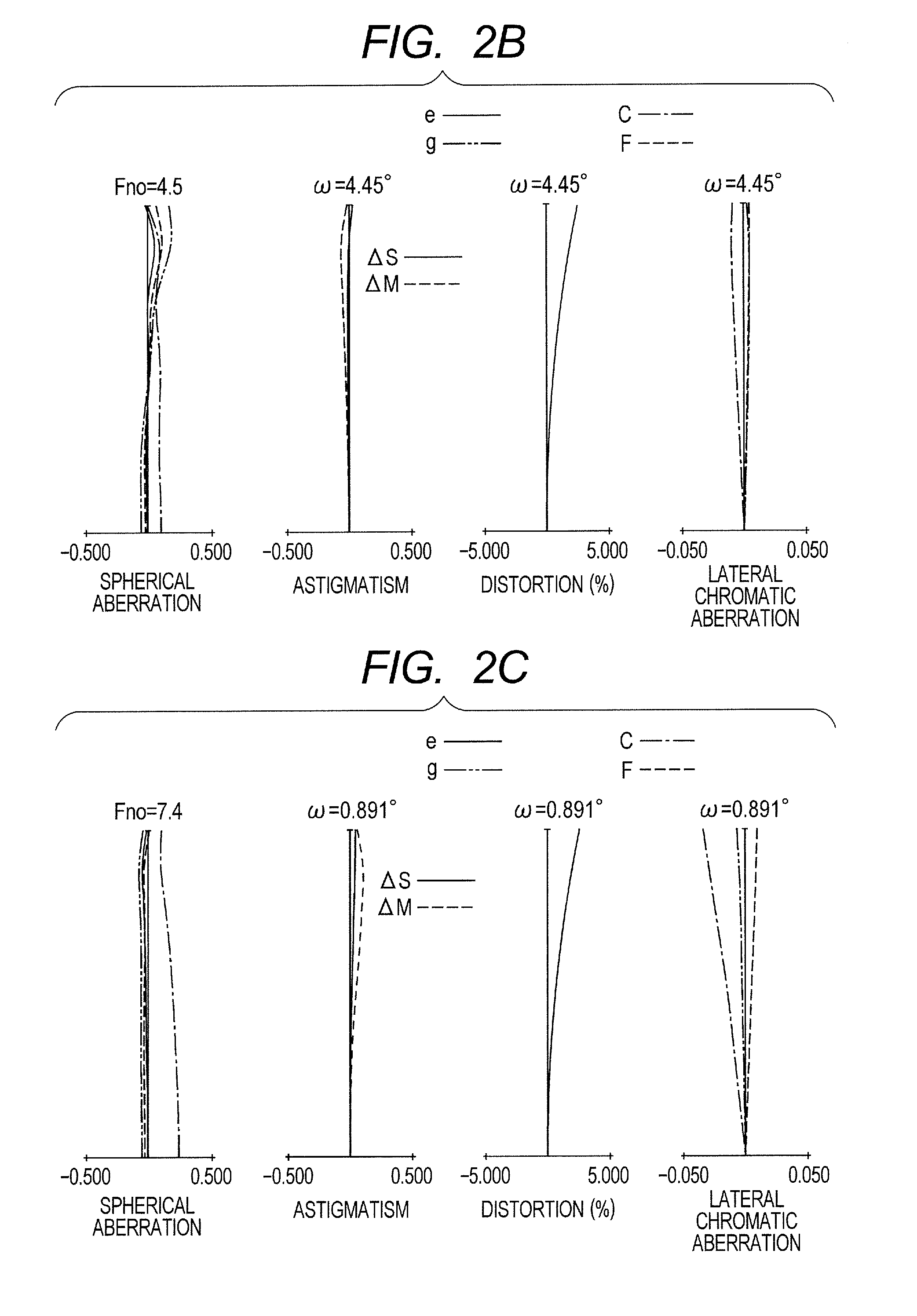
[0077]FIG. 1 is a lens cross-sectional view when focus is at an object at infinity at the wide angle end (short focal length end) in Numerical Embodiment 1 as Embodiment 1 of the present invention. FIGS. 2A, 2B, and 2C are aberration diagrams when focus is at infinity at the wide angle end, when focus is at infinity at a zoom position having a focal length of 200 mm, and when focus is at infinity at the telephoto end, respectively. In the lens cross-sectional views, the left side is a subject (object) side (front side), and the right side is the image side (rear side). A first lens unit U1 having a positive refractive power that does not move includes, in order from the object side to the image side, a first sub lens unit U11 having a positive refractive power, a second sub lens unit U12 having a positive refractive power, and a third sub lens unit U13 having a negative refractive power. A second lens unit U2 having the negative refractive power that moves during zooming is moved on...

embodiment 2

[0081]First to fourth lens units in Numerical Embodiment 2 as Embodiment 2 are described. In Numerical Embodiment 2, the first lens unit U1 corresponds to the first to thirteenth lens surfaces, and includes, in order from the object side to the image side, the first sub lens unit having a positive refractive power and the second sub lens unit having a negative refractive power. The first sub lens unit having the positive refractive power includes, in order from the object side to the image side, two positive lenses, a negative lens, and two positive lenses. The second sub lens unit includes a cemented negative lens formed by cementing a positive lens and a negative lens, and the second sub lens unit is moved in the optical axis direction to perform focus adjustment. The second lens unit U2 corresponds to the fourteenth to twenty-third lens surfaces in Numerical Embodiment 2, and includes, in order from the object side to the image side, a cemented negative lens formed by cementing a...

embodiment 3

[0083]First to fourth lens units in Numerical Embodiment 3 as Embodiment 3 are described. In Numerical Embodiment 3, the first lens unit U1 corresponds to the first to fourteenth lens surfaces, and includes, in order from the object side to the image side, the first sub lens unit having a positive refractive power, the second sub lens unit having a positive refractive power, and a third sub lens unit having a negative refractive power. The first sub lens unit having the positive refractive power includes, in order from the object side to the image side, two positive lenses and a negative lens. The second sub lens unit having the positive refractive power includes, in order from the object side to the image side, a positive lens, and a cemented positive lens formed by cementing a positive lens and a negative lens, and the second sub lens unit is moved in the optical axis direction to perform focus adjustment. The third sub lens unit includes a cemented negative lens formed by cementi...


PUM


Abstract

A zoom lens includes, in order from an object side to an image side: a first lens unit having a positive refractive power that does not move for zooming; a second lens unit having a negative refractive power that moves during zooming; a third lens unit having a positive refractive power that moves during zooming; and at least one lens unit having a positive refractive power, and focal lengths of the zoom lens at a wide angle end and a telephoto end, a maximum value of a half angle of field at the wide angle end, and products of lateral magnifications of lens units arranged on the image side of the third lens unit in a state in which focus is at infinity at the telephoto end and the wide angle end are appropriately set.

Description

BACKGROUND OF THE INVENTION[0001]1. Field of the Invention[0002]The present invention relates to a zoom lens suitable for a television camera, a video camera, a film camera, a broadcasting television camera, and a movie camera, and more particularly, to a telephoto zoom lens having a large aperture and a high magnification.[0003]2. Description of the Related Art[0004]In a case where a nature program or the like is photographed for television (for example, an animal, a bird, or the like is photographed outdoors from a long distance), a zoom lens that is usable up to a focal length in a super telephoto range at a high magnification (for example, a high magnification of 7× or more and a half angle of field of 3 degrees or less at a telephoto end) and has high optical performance is required. In such photographing, a camera is often carried on a shoulder for photographing, and hence a zoom lens that is smaller in size and weight and has good portability is required. Moreover, in recent ...

Claims


Application Information

Patent Timeline
Patent Type & Authority Applications(United States)
IPC IPC(8): G02B15/173G02B15/16
CPCG02B15/16G02B15/173G02B15/145113G02B15/163G02B15/167
Inventor TAKEMOTO, SHOICHI
Owner CANON KK
Why Eureka
Try Eureka