
Robot

Active Publication Date: 2015-11-12
SEIKO EPSON CORP
View PDF7 Cites 5 Cited by
  • Summary
  • Abstract
  • Description
  • Claims
  • Application Information

AI Technical Summary

Benefits of technology

The invention provides a robot that can reduce vibrations in its moving parts.

Problems solved by technology

However, the increase in the rigidity of the base causes an increase in costs of the base itself.
Further, a rotating range of the robot arms is limited centering on the position of the base.
However, in the ceiling hanging SCARA robot in the past, as a stroke amount of the movable shaft section is increased, for example, the connecting section of the first arm and the second arm also increases and vibration tends to occur in the movable shaft section.
When the vibration occurs in the movable shaft section, deterioration in working accuracy is caused.

Method used


Image

  • Robot
  • Robot
  • Robot

Examples


Embodiment Construction

[0042]An embodiment of the invention is explained in detail below with reference to the drawings.

[0043]Note that the invention is not limited to the embodiment explained below and can be changed and carried out as appropriate without departing from the spirit of the invention. In the drawings referred to in the following explanation, in order to clearly show components, the components are sometimes schematically shown. Some components are shown with scales of dimensions thereof varied.

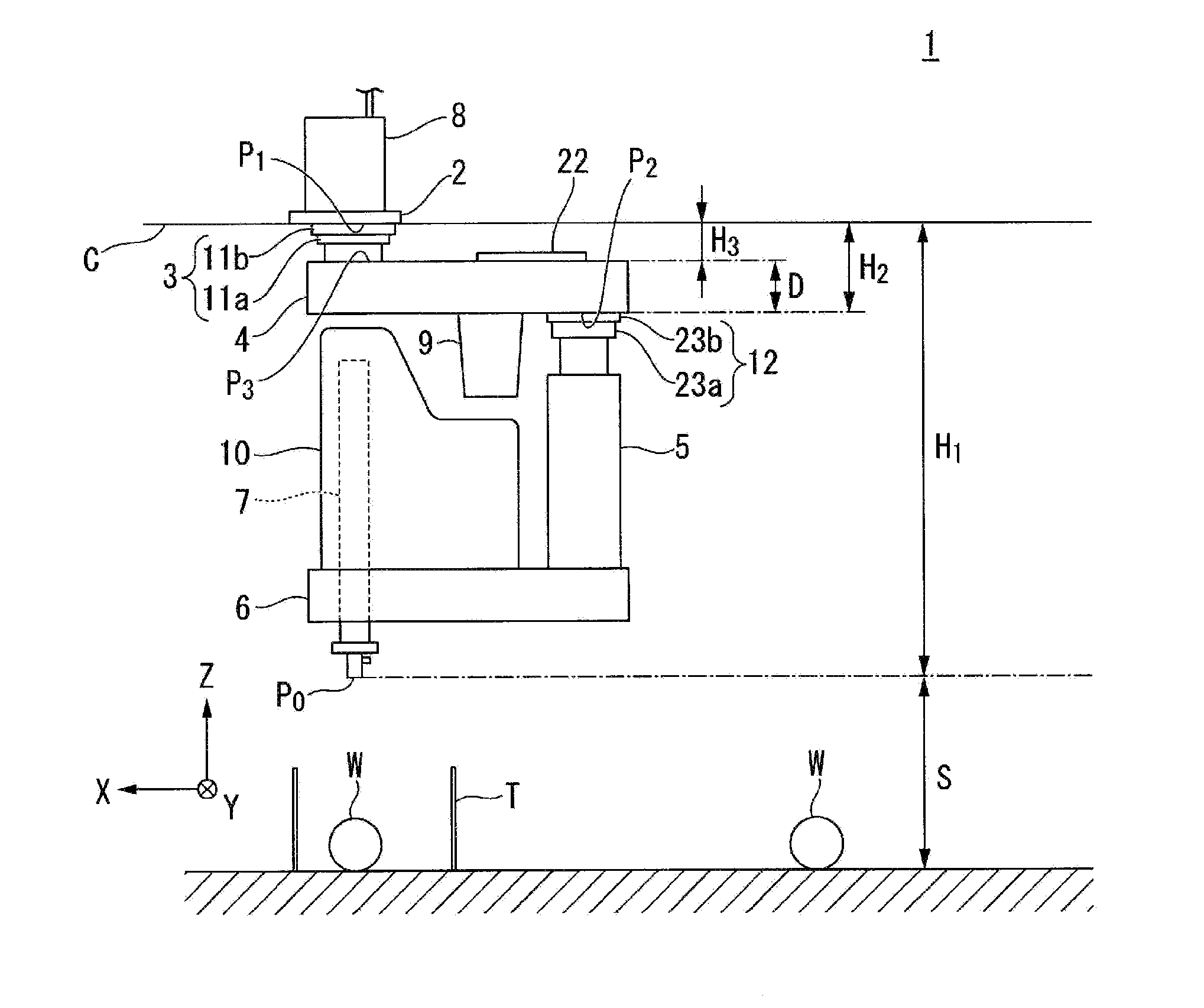
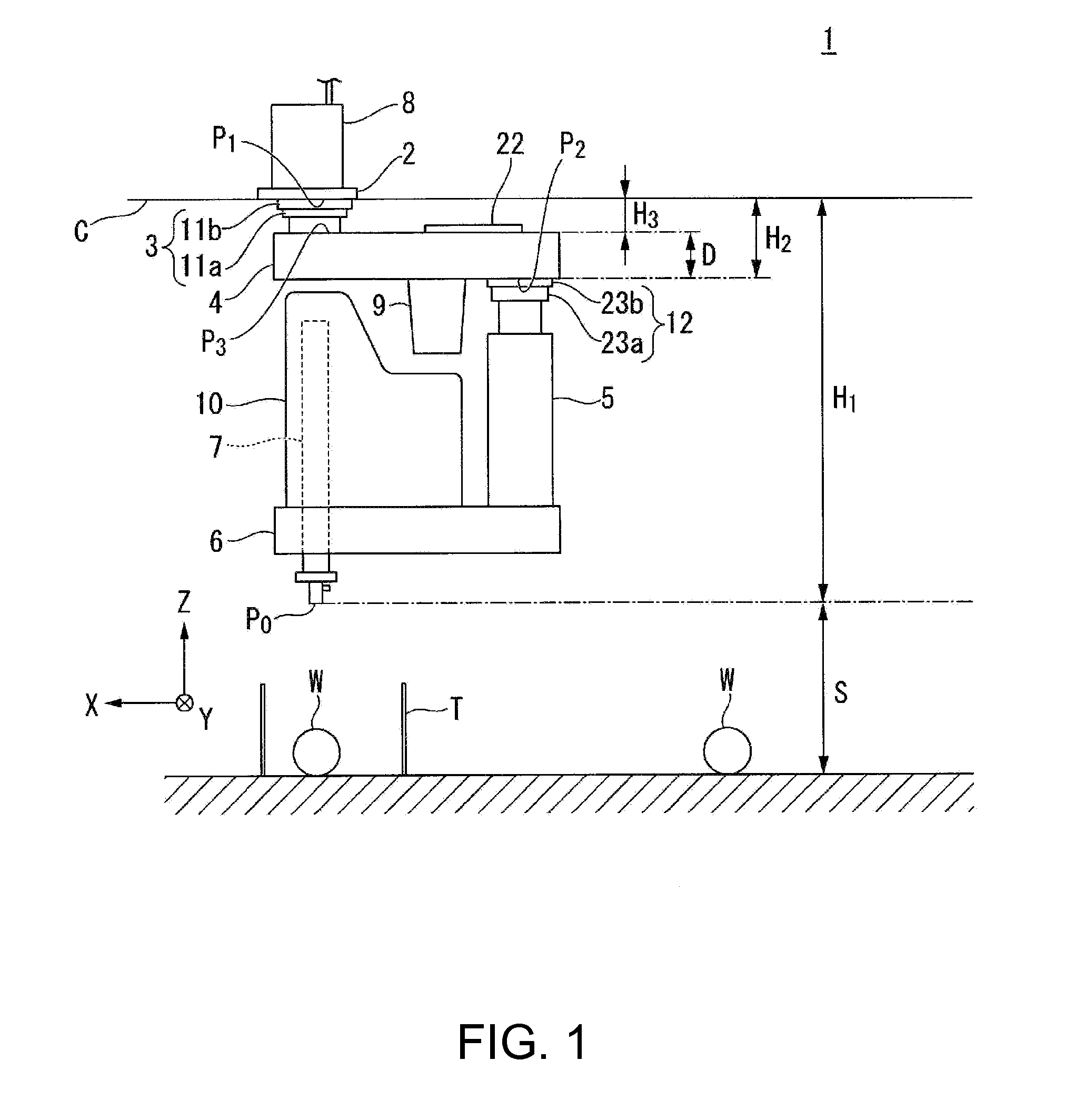
[0044]First, as an embodiment of the invention, for example, a ceiling hanging SCARA robot 1 shown in FIG. 1 is explained. Note that FIG. 1 is a side view showing the schematic configuration of the ceiling hanging SCARA robot 1. In the following explanation, an XYZ rectangular coordinate system is set. Positional relations among members are explained with reference to the XYZ rectangular coordinate system. Specifically, the left-right direction of the paper surface in FIG. 1 is represented as an X-axis...


PUM


Abstract

A robot includes a base, a first arm rotatably provided on the base via a first connecting section, a second arm rotatably provided on the first arm via a second connecting section, and a movable shaft section provided in the second arm and movable with respect to the second arm. When a movable range of the movable shaft section is represented as S and the height between a distal end of the movable shaft section on the opposite side of the first arm at the time when the movable shaft section moves to the first arm side most with respect to the second arm and a first connection surface, which is a connection surface of the base and the first connecting section, is represented as H1, a relation H1≦3S is satisfied.

Description

BACKGROUND[0001]1. Technical Field[0002]The present invention relates to a robot.[0003]2. Related Art[0004]In recent years, automation by industrial robots is ongoing for manufacturing such as automotive body manufacturing. As the industrial robots, industrial robots including robot arms such as a horizontally articulated robot (a SCARA robot) and a vertically articulated robot have been widely used.[0005]In assembly work by such industrial robots, a plurality of robots are set to surround an assembly workbench on a setting surface on which the assembling workbench is set. The plurality of robots perform assembly work for an assembly on the assembly workbench while cooperating with one another.[0006]In the assembly work by the plurality of robots, it is necessary to keep a horizontal state of the robots. As measures for keeping the horizontal state of the robots, the rigidity of a base fixed on the setting surface for the robots is increased. However, the increase in the rigidity of...

Claims


Application Information

Patent Timeline
IPC IPC(8): B25J9/00B25J9/04
CPCB25J9/0018Y10T74/20317Y10T74/20305B25J9/042
Inventor HAHAKURA, SEIJIYOKOTA, MASATO
Owner SEIKO EPSON CORP
Learn More