
Ceiling mounted robot

Inactive Publication Date: 2015-11-12
SEIKO EPSON CORP
View PDF4 Cites 11 Cited by
  • Summary
  • Abstract
  • Description
  • Claims
  • Application Information

AI Technical Summary

Benefits of technology

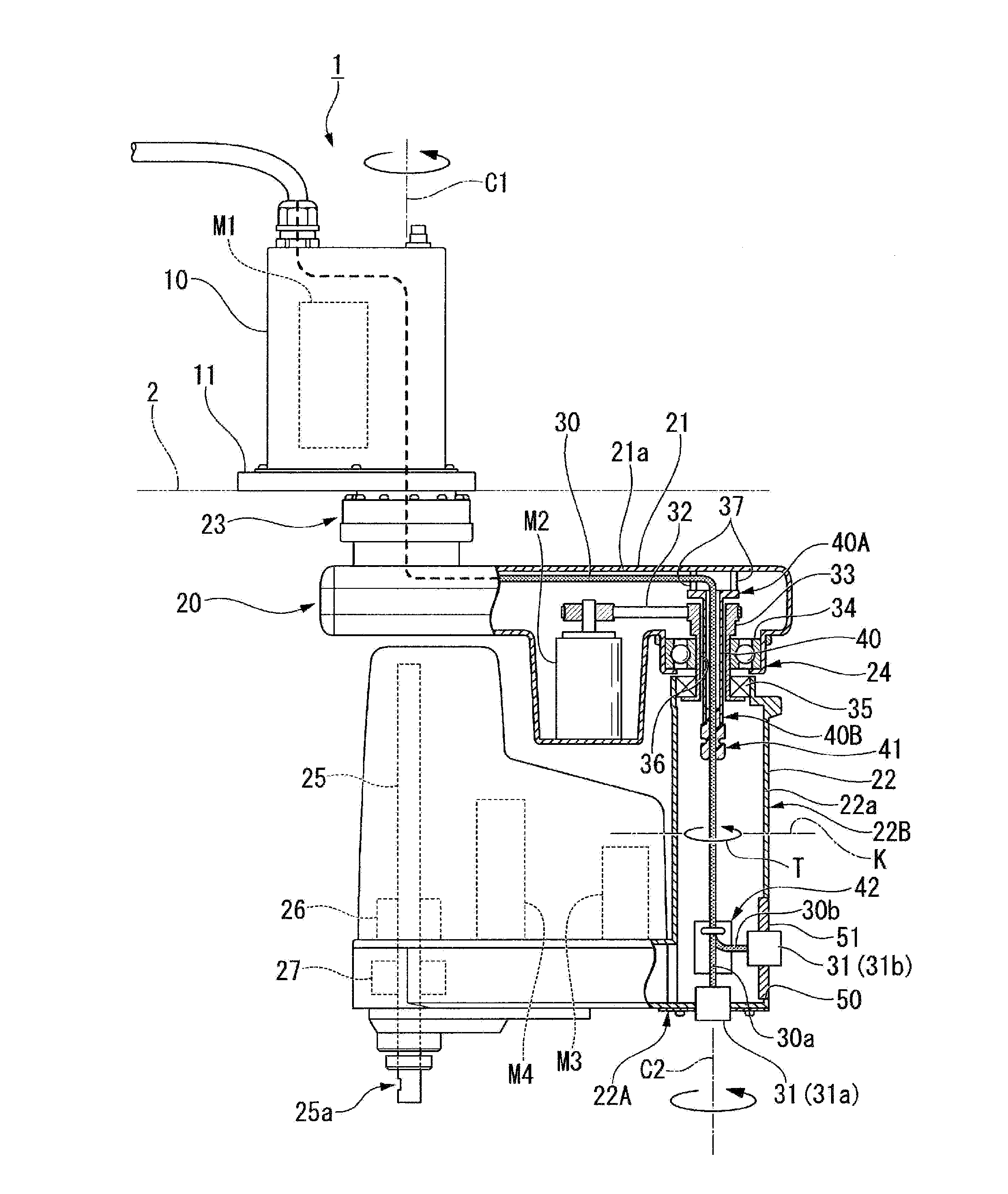
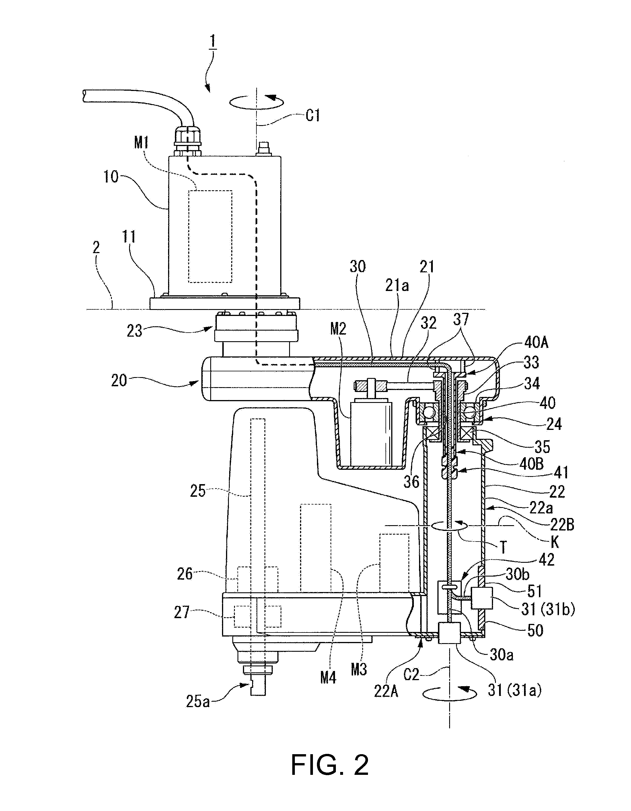
This invention relates to a ceiling mounted robot that can reduce the strain on its wiring. The robot has a pipe portion that passes through the first and second arm portions, allowing the wiring to pass through. The wiring is fixed to the end of the pipe portion and the second arm portion to prevent rubbing and twisting. The robot also has an opening in the second arm portion for easy access and maintenance. The technical effect of this invention is to increase the gap between the first and second fixing points and decrease the strain on the wiring.

Problems solved by technology

However, since a ceiling mounted robot has a wide movement region, when a camera or the like is installed on an articulated arm, and a relay cable is directly connected to an outside device, the relay cable may become entangled with the articulated arm, and a load may be applied to the relay cable.
Here, since the wiring passing through the pipe portion is unstable, the wiring is fixed to the second end portion of the pipe portion and the second arm portion.

Method used


Image

  • Ceiling mounted robot
  • Ceiling mounted robot
  • Ceiling mounted robot

Examples


Embodiment Construction

[0026]Hereinafter, a ceiling mounted robot according to an embodiment of the invention will be described with reference to the accompanying drawings.

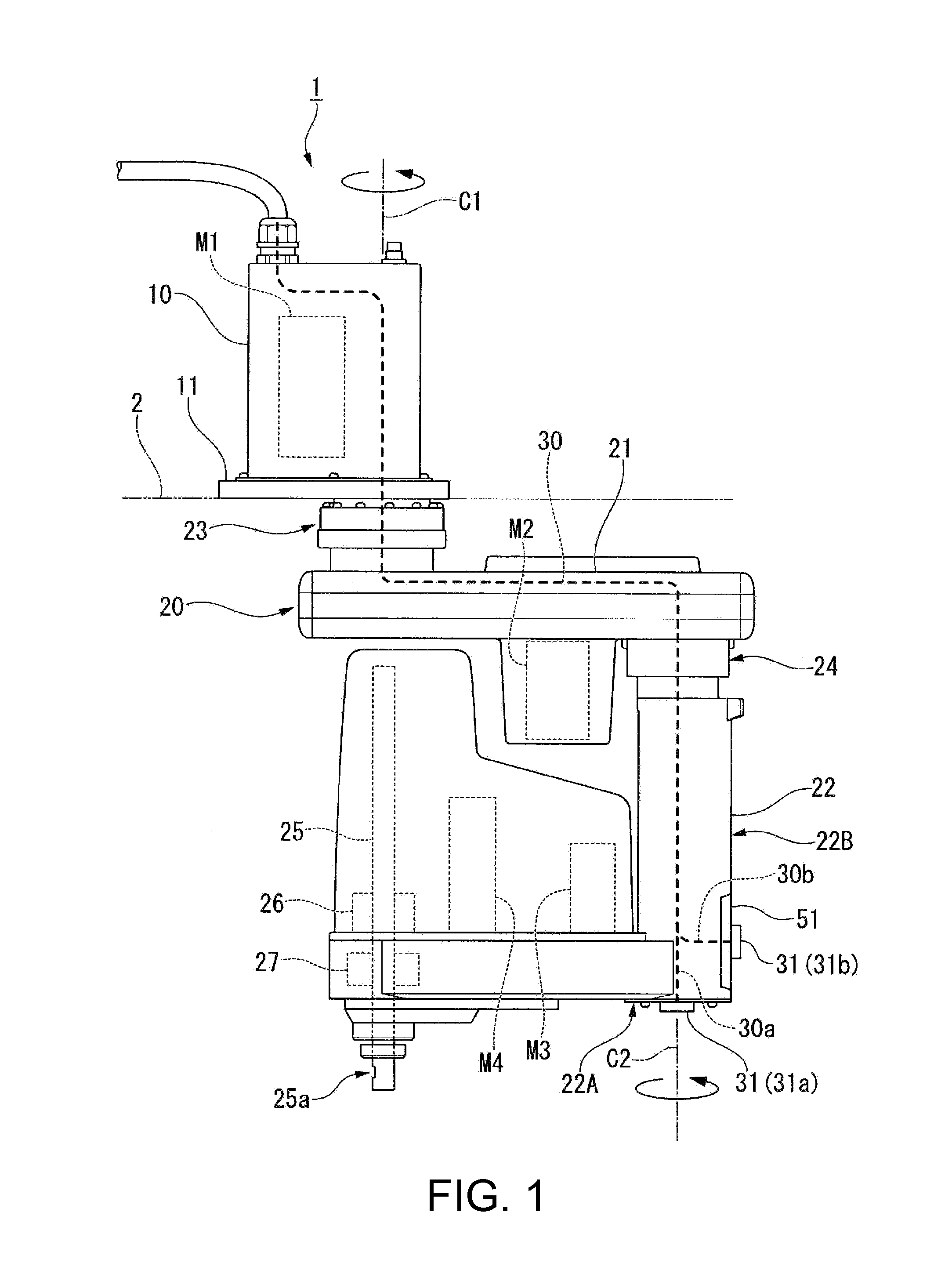
[0027]FIG. 1 is a view illustrating the entire configuration of a ceiling mounted robot 1 according to the embodiment of the invention.

[0028]As illustrated in FIG. 1, the ceiling mounted robot 1 of the embodiment is a selective compliance articulated robot arm (SCARA) robot that is suspended from a ceiling surface 2. The ceiling mounted robot 1 includes a base (first member) 10, and an articulated arm 20 that has a movement envelope of at least 360° around the base 10. For example, in the articulated arm 20 of the embodiment, a first arm portion 21 can turn at ±225°, and a second arm portion 22 can turn at ±225°.

[0029]The base 10 has an installation portion 11. The installation portion 11 is a plate-like member attached to a lower portion of the base 10. The installation portion 11 is installed on the ceiling surface 2. For example, the...


PUM


Abstract

A ceiling mounted robot includes a first member; a first arm portion that is turnably provided on the first member via a first joint portion; a second arm portion that is turnably provided on the first arm portion via a second joint portion; a hollow pipe that has a first end portion fixed to the first arm portion, and a second end portion inserted into the second arm portion; a first fixing portion that fixes a wiring inserted into the hollow pipe to the second end portion of the pipe portion; and a second fixing portion that fixes the wiring to the second arm portion.

Description

BACKGROUND[0001]1. Technical Field[0002]The present invention relates to a ceiling mounted robot.[0003]2. Related Art[0004]Typically, an industrial robot with an articulated arm is installed on the ground, and for example, is configured in such a manner as to assemble a predetermined structural body on a work bed. The movement region of the articulated arm excludes a region in which the articulated arm interferes with a base of the industrial robot installed on the ground.[0005]The ceiling mounted robot is an industrial robot, the base of which is installed on a ceiling so as to avoid interference between the articulated arm and the base. This articulated arm can have a wide movement region around the base of 360° or greater.[0006]A ceiling mounted SCARA robot disclosed in International Publication No. 2012 / 029173 is known as an example of such a ceiling mounted robot. The ceiling mounted robot has a base; a first arm portion that is turnably provided on the base via a first joint p...

Claims


Application Information

Patent Timeline
IPC IPC(8): B25J18/00B25J9/04B25J9/00
CPCB25J18/00B25J9/0018Y10T74/20305Y10S901/27Y10S901/14B25J9/044B25J19/0029
Inventor HAHAKURA, SEIJIYOKOTA, MASATO
Owner SEIKO EPSON CORP
Learn More