Observation supporting apparatus and observation supporting method

a technology of supporting apparatus and supporting method, which is applied in the direction of speed measurement using gyroscopic effects, instruments, surveying and navigation, etc., can solve the problems of large error in the orbit estimation based on the coordinate points, difficult to detect the three coordinate points and difficult to estimate the orbit of the object moving at high speed. , to achieve the effect of improving the discovery efficiency of the unknown obj

Active Publication Date: 2015-11-12
MITSUBISHI HEAVY IND LTD
View PDF3 Cites 10 Cited by
  • Summary
  • Abstract
  • Description
  • Claims
  • Application Information

AI Technical Summary

Benefits of technology

[0021]Also, the discovery efficiency of the unknown object can be improved.

Problems solved by technology

However, because the viewing angle is narrow in the optical observation equipment, it is difficult to detect three coordinate points of the object moving at high speed through once observation.
Also, even if it is supposed that the three coordinate points of the moving object can be detected through the once observation by an observation equipment having the narrow viewing angle, the orbit estimated based on the coordinate points contains a large error.
In this way, because the viewing angle of the optical telescope is narrow, it is difficult to estimate the orbit of the object moving at high speed.
However, because whether the monitoring object is known or unknown is determined after a specifiable orbit (whole orbit) is estimated based on the orbit 6 matters, the efficiency of the discovery of the unknown object is low.

Method used


Image

  • Observation supporting apparatus and observation supporting method
  • Observation supporting apparatus and observation supporting method
  • Observation supporting apparatus and observation supporting method

Examples


first embodiment

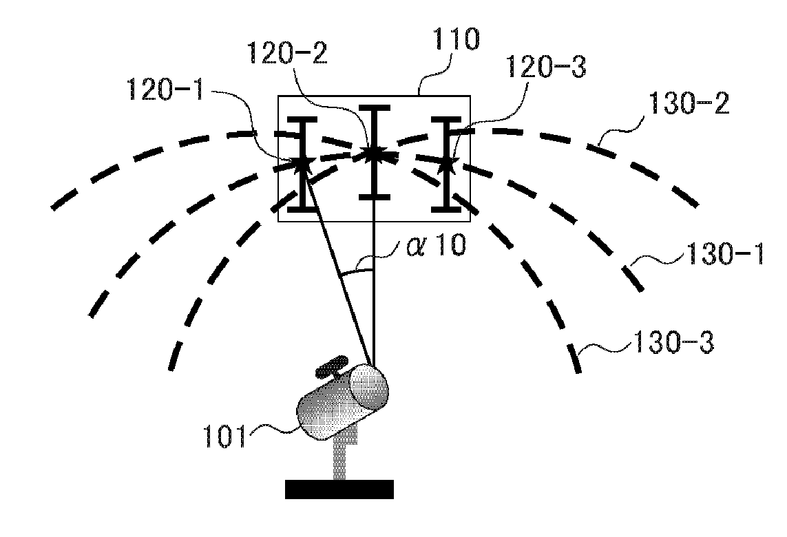
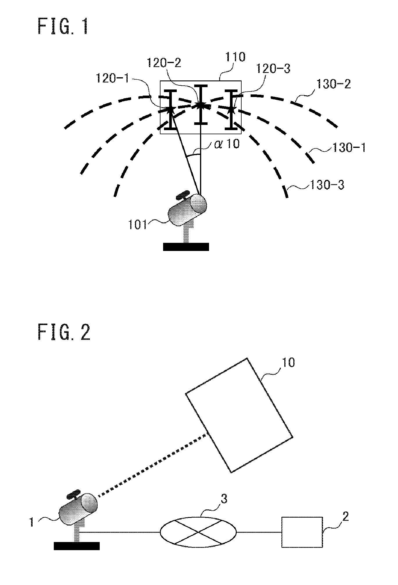
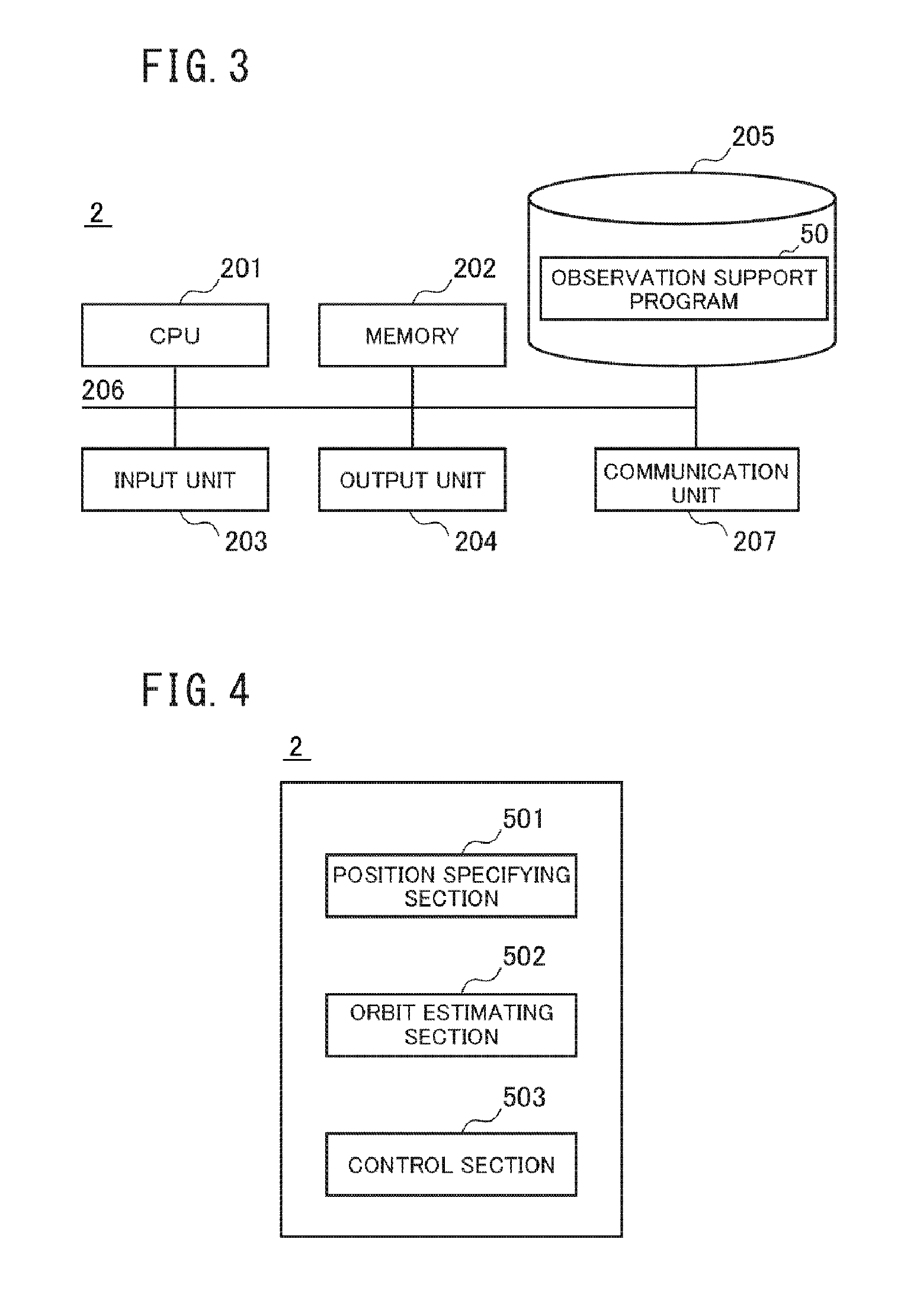
[0047]Referring to FIG. 4 to FIG. 7, the observation system and the observation supporting apparatus 2 according to a first embodiment of the present invention will be described. The observation supporting apparatus 2 of the first embodiment calculates an estimate orbit 100 in a viewing field 10 from coordinate points and the shape of a bright line of the observed moving object and sets the observation direction of the optical telescope 1 onto the extension of the estimate orbit 100. FIG. 4 is a functional block diagram showing a configuration example of the observation supporting apparatus 2 of the first embodiment. Referring to FIG. 4, the CPU 201 in the first embodiment realizes each function of the position specifying section 501, the orbit estimating section 502 and the control section 503 by executing the observation support program 50.

[0048]The position specifying section 501 analyzes the image imaged by the optical telescope 1 and specifies a moving object. For example, when...

second embodiment

[0054]Referring to FIG. 8 to FIG. 10, the observation system and the observation supporting apparatus 2 according to the second embodiment of the present invention will be described. The observation supporting apparatus 2 of the second embodiment estimates the whole orbit of the moving object (e.g. the orbit around the earth) by using the coordinate points of the moving object detected in the large observation elongation while tracking the moving object in the similar way to the first embodiment. FIG. 8 is a functional block diagram showing the configuration example of the observation supporting apparatus 2 in the second embodiment. Referring to FIG. 8, the CPU 201 in the second embodiment executes the observation support program 50 to realize each function of the position specifying section 501, the orbit estimating section 502 and the control section 503.

[0055]The position specifying section 501 analyzes the image which is imaged by the optical telescope 1 and specifies the moving...

third embodiment

[0063]Referring to FIG. 11 to FIG. 13, the observation system and the observation supporting apparatus 2 according to a third embodiment of the present invention will be described. The observation supporting apparatus 2 of the third embodiment determines whether (the orbit of) the moving object is known or unknown based on the comparison result of the estimate orbit in the viewing field 10 and known orbits stored in the database. FIG. 11 is a functional block diagram showing the configuration example of the observation supporting apparatus 2 of the third embodiment. Referring to FIG. 11, the CPU 201 in the third embodiment executes the observation support program 50 to realize each of the functions of the position specifying section 501, the orbit estimating section 502 and the orbit determining section 504.

[0064]The position specifying section 501 analyzes the image data imaged by the optical telescope 1 and specifies the moving object, like the first embodiment. The orbit estimati...


PUM


Abstract

An observation supporting apparatus includes a position specifying section which specifies a coordinate point of a moving object detected in a viewing field through once observation. An orbit estimating section calculates an estimate orbit of the moving object in the viewing field based on the specified coordinate points. Data necessary to estimate the position of the moving object out of the viewing field is acquired using the estimate orbit by the orbit estimating section.

Description

TECHNICAL FIELD[0001]The present invention is related to an observation supporting apparatus and an observation supporting method, and more particularly, to an observation supporting apparatus and an observation supporting method which estimate a position of a moving object which moves on an orbit.BACKGROUND ART[0002]When estimating an orbit of an object which moves on an orbit (e.g. an artificial satellite and space debris) by using an optical observation equipment (e.g. an optical telescope), at least three coordinate points need to be specified. However, because the viewing angle is narrow in the optical observation equipment, it is difficult to detect three coordinate points of the object moving at high speed through once observation. Also, even if it is supposed that the three coordinate points of the moving object can be detected through the once observation by an observation equipment having the narrow viewing angle, the orbit estimated based on the coordinate points contains...

Claims


Application Information

Patent Timeline
Patent Type & Authority Applications(United States)
IPC IPC(8): G01B11/00
CPCG01B11/002G01S3/78
Inventor MORIOKA, TOMOYAYAMADA, TAKAHIROHOSHINO, TOMOHIRO
Owner MITSUBISHI HEAVY IND LTD
Why Eureka
Try Eureka