Tap-Scan Bridge Damage Detection System

Active Publication Date: 2015-11-12
CHINA ROAD & BRIDGE +1
View PDF0 Cites 8 Cited by
  • Summary
  • Abstract
  • Description
  • Claims
  • Application Information

AI Technical Summary

Benefits of technology

[0020]The tap-scan bridge damage detection system of embodiments of the invention has a strict theoretical basis. Detection signals may be obtained by scanning the to-be-detected bridge without requiring traffic blocking. The damage information of the bridge may be obtained directly from the detection signals without requiring the a priori damage information of the bridge. Thus, the operation is simple and easy to implement with high efficiency. By means of the tap-scan bridge damage detection system of embodiments of the invention, the damage status of a bridge may be readily learnt with convenience, so that potential risks at the bridge may be discovered in time, thus avoiding the occurrence of bridge accidents.
[0021]The tap-scan bridge damage detection system of embodiments of the invention is high in sensitivity, in which the detection requires shorter time without special detection conditions and yields high accuracy at a low cost, and as compared to the aforementioned existing bridg

Problems solved by technology

These bridges in use are constantly subjected to erosive impacts from the environment, such as temperature changes, strong winds and rainfalls, plus repeated and long-term actions from vehicle loads and strikes, and parts of the bridges even suffer from natural disasters like floods, earthquakes and so on, so over years of use, different degrees of fatigue effects and aging phenomena commonly appear in the bridges.
As bodies of the bridges accumulate a great deal of exterior damages, many of them have become “danger bridges” in a certain sense.
Bridges of such kind, located worldwide, have had quite a few instances of collapse, which posed a great threat to the security of human lives and properties.
Thus, it is significant to detect damages of bridge in real time and effectively.
From the perspectives of the implementation period and the detection accuracy, the bridge detection comprises mainly the two modes of periodic inspection and real-time inspection: for the periodic inspection, such as visual inspection with i

Method used


Image

  • Tap-Scan Bridge Damage Detection System
  • Tap-Scan Bridge Damage Detection System
  • Tap-Scan Bridge Damage Detection System

Examples


Example

[0031]1 Mobile cart[0032]10 Driving apparatus[0033]11 Cart body[0034]12 Front wheel[0035]13 Rear wheel[0036]14 Through-shaft[0037]2 Tap subsystem[0038]21 Tap apparatus[0039]22 Tap controlling apparatus[0040]3 Signal acquisition subsystem[0041]31 Signal pickup apparatus[0042]4 Signal processing apparatus[0043]L Cart body axis

DETAILED DESCRIPTION OF THE INVENTION

[0044]Exemplary embodiments of the present disclosure are described hereinafter in more detail with reference to the drawings. Although the drawings display the exemplary embodiments of the present disclosure, it is to be understood that the present disclosure may be carried out in various forms and should not be confined to the herein elucidated embodiments. Instead, these embodiments are provided for a more thorough understanding of the disclosure and for enabling to convey the scope of the present disclosure more comprehensively to the persons skilled in the art.

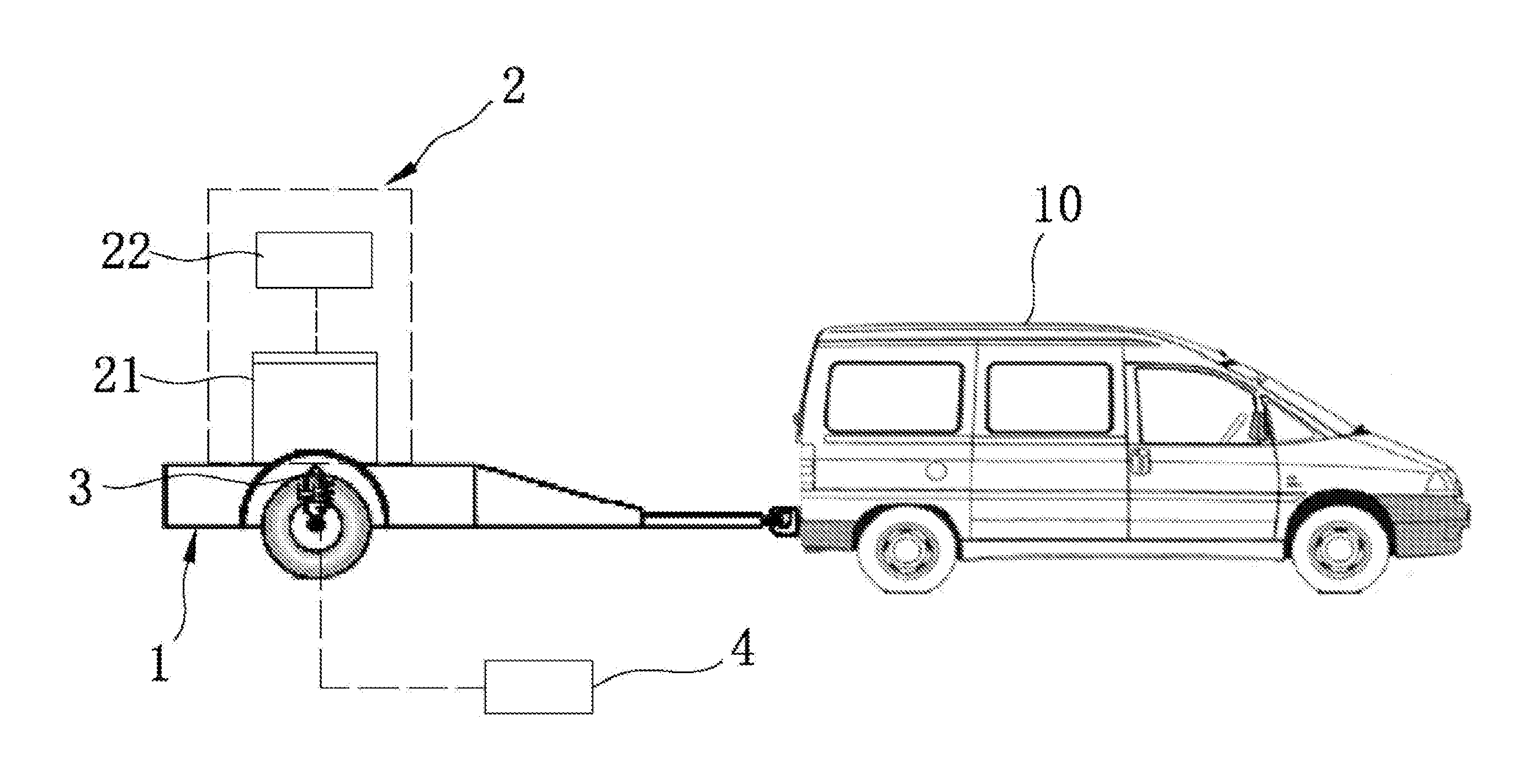
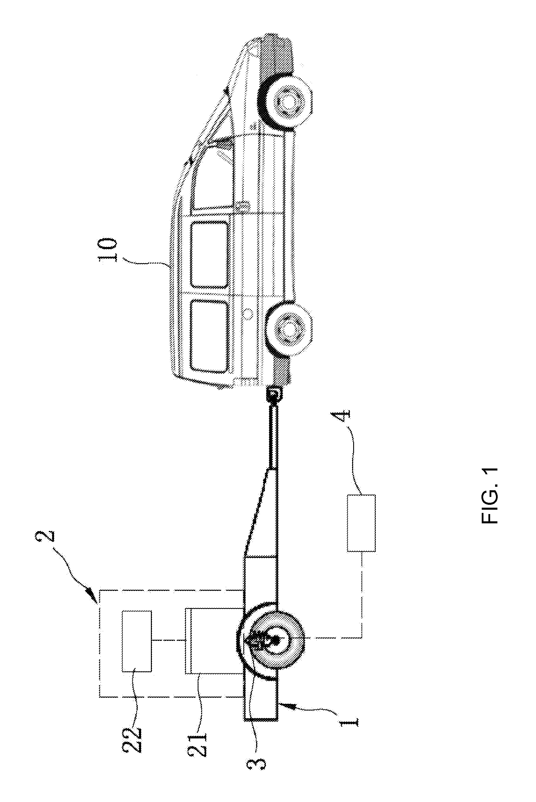
[0045]Please refer to FIG. 1, which is a composition schematic...


PUM


Abstract

A tap-scan bridge damage detection system comprises: a mobile cart (1) capable of moving on a to-be-detected bridge; a tap subsystem (2) mounted on the mobile cart (1) and used for applying a tap load to the to-be-detected bridge; a signal acquisition subsystem (3) mounted on the mobile cart and used for acquiring a response signal transferred from the to-be-detected bridge to the mobile cart; and a signal processing apparatus (4) connected to the signal acquisition subsystem (3) and used for receiving and processing a signal acquired by the signal acquisition subsystem (3), and outputting the bridge damage information processed result. The tap-scan bridge damage detection system can detect bridge damage in a simple, convenient, efficient and accurate manner.

Description

CROSS-REFERENCE TO RELATED APPLICATIONS[0001]The present invention is the national stage application of the PCT International Application, Serial No. PCT / CN2013 / 090702, filed on Dec. 27, 2013, which claims the priority to the Chinese patent application, serial number 201210584811.1, filed on Dec. 28, 2012, whose contents are incorporated by reference in their entirety herein.FIELD OF THE INVENTION[0002]Embodiments of the invention relates to a bridge damage detection system and, in particular, to a tap-scan bridge damage detection system.BACKGROUND[0003]With the progress of science and technology as well as increasing demands in traffic and transportation, the number of bridges for use on various roads and in rail transit has grown at great speed. These bridges in use are constantly subjected to erosive impacts from the environment, such as temperature changes, strong winds and rainfalls, plus repeated and long-term actions from vehicle loads and strikes, and parts of the bridges ev...

Claims


Application Information

Patent Timeline
IPC IPC(8): G01M5/00G01M7/08
CPCG01M5/0008G01M7/08G01M5/0033G01M5/0066G01M5/0075G01N29/045G01N29/265G01N29/46G01N2291/0232
Inventor ZHANG, JIANCHUXIANG, ZHIHAILIU, HONGLI, ZHIHUAILU, QIUHAISUN, YAOGUOWANG, YANHUALI, LIANYOUSHEN, ZHAOPU
Owner CHINA ROAD & BRIDGE
Why Eureka
Try Eureka