Method and apparatus for determining a need for a change in a pixel density requirement due to changing light conditions

a technology of pixel density and light conditions, applied in the field of camera surveillance, can solve the problems of only valid pixel density requirements and density requirements that may not be enough to ensure legal validity of objects, and achieve the effect of increasing monitoring efforts

Active Publication Date: 2015-11-12
AXIS
View PDF13 Cites 5 Cited by
  • Summary
  • Abstract
  • Description
  • Claims
  • Application Information

AI Technical Summary

Benefits of technology

[0026]Another example of an event is to overlay an indication on the images captured by the camera showing in which part of the field of view the identification may be correctly done under the current light conditions. Yet another example of an event is to automatically direct another movable camera towards the interesting monitoring area to increase the monitoring efforts.

Problems solved by technology

However, the pixel density requirements as for example recommended by police authorities are only valid under optimal light conditions.
When scene conditions change, for example when the light level changes, the recommended pixel density requirement may not be enough to ensure a legally valid object identification—a higher pixel density may well be required.

Method used


Image

  • Method and apparatus for determining a need for a change in a pixel density requirement due to changing light conditions
  • Method and apparatus for determining a need for a change in a pixel density requirement due to changing light conditions
  • Method and apparatus for determining a need for a change in a pixel density requirement due to changing light conditions

Examples


Embodiment Construction

[0045]The present invention will now be described more fully hereinafter with reference to the accompanying drawings, in which currently preferred embodiments of the invention are shown. The systems and devices disclosed herein will be described during operation.

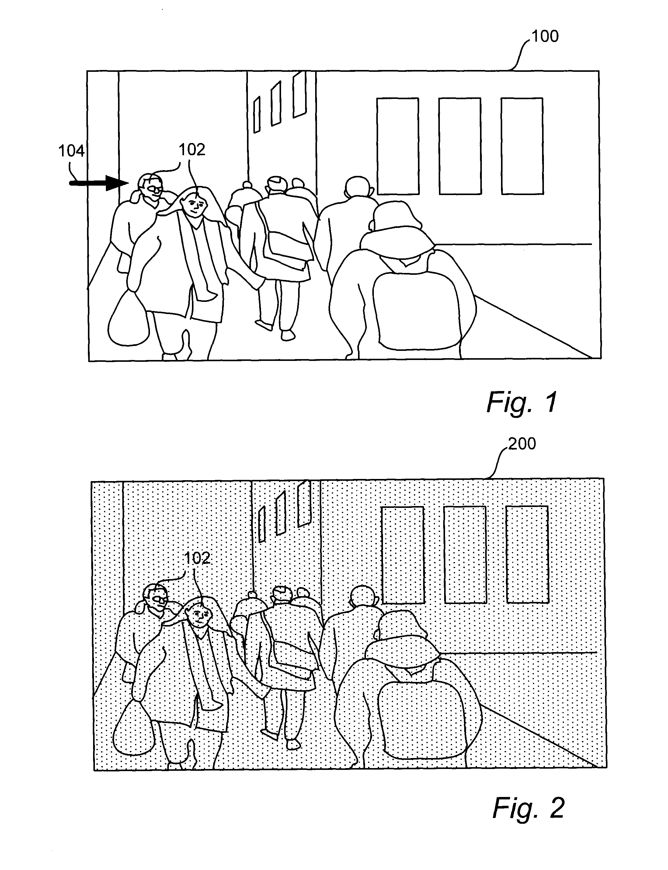
[0046]FIG. 1 illustrates an image 100 of a field of view of a surveillance camera. The image 100 includes objects 102, in this case faces, which potentially need to be identified from images captured by the camera. The image 100 is assumed to be captured during day time when the light condition, i.e. the light level, is optimal or close to optimal, such as at least 100 lx. It is assumed that the gain of the camera is equal to 0 dB under such conditions.

[0047]Under these light conditions, there is a certain pixel density requirement which enables identification of the objects 102 in the image 100. For example, there may be a requirement that a face needs to be captured at 250 pixels / m in order to ensure correct identification...


PUM


Abstract

There is provided a method for determining a need for a change in a pixel density requirement due to changing light conditions. The pixel density requirement specifies a pixel density which enables identification of an object in images captured by a camera. The method comprises receiving and monitoring (S02) a camera setting which is indicative of a light condition to which the camera is subjected and which affects the quality of images captured by the camera, and determining (S06) that there is a need for a change in the pixel density requirement upon detection (S04) of a change in the camera setting. The camera setting includes at least one of a gain and an exposure time used by the camera when capturing images.

Description

TECHNICAL FIELD[0001]The present invention relates to the field of camera surveillance, and, in more detail, to identification of objects in accordance with a pixel density requirement in images captured by a camera. In particular, it relates a method, an apparatus, and a system for determining a need for a change in a pixel density requirement due to changing light conditions.BACKGROUND[0002]Camera surveillance has become more and more common. Images captured by surveillance cameras are for example used as evidence in police investigations and legal trials for the purpose of identification of objects, such as the face of a suspect or the numbers on a license plate.[0003]In order for the object identification to be valid as legal evidence, the resolution of the object in the image must be high enough, i.e. the object must cover a certain amount of pixels in the image. This is usually expressed in terms of a pixel density requirement specifying a pixel density (e.g. measured in pixel...

Claims


Application Information

Patent Timeline
Patent Type & Authority Applications(United States)
IPC IPC(8): H04N5/232H04N5/262
CPCH04N5/23296H04N5/23245H04N5/2628G03B7/00H04N7/181G08B29/18H04N23/72H04N23/69H04N23/71H04N23/667
Inventor STAHL, PER
Owner AXIS
Why Eureka
Try Eureka