Haptic devices for intraocular lens

a technology of haptic devices and intraocular lenses, which is applied in the field of haptic devices for intraocular lenses, can solve the problems of minor distortions of optics, inability to provide the desired visual acuity, and reduced or eliminated the ability of the eye to change focus, so as to maximize the natural circulation of aqueous humor, minimize common post-surgical problems, and maximize the effect of focal flexibility

Active Publication Date: 2015-11-19
ANEW IOL TECH
View PDF4 Cites 7 Cited by
  • Summary
  • Abstract
  • Description
  • Claims
  • Application Information

AI Technical Summary

Benefits of technology

[0024]The present invention overcomes the problems and disadvantages associated with current strategies and designs and provides new haptic devices and methods for positioning an intraocular lens in the eye, as well as designs for specific functionality to provide optimal focal flexibility and mitigate common post surgical problems.
[0025]An embodiment of the invention is directed to haptic devices that are comprised of two parallel rings connected by a pillar or several pillars of haptic material, between which an optic is suspended, such that the anterior ring makes contact with the anterior capsule at some distance from the lens equator, and the posterior ring makes contact with the posterior capsule at some distance from the lens equator, the rings connected to each other and to the framework supporting the lens optic by means of ribbons and struts that maintain suitable spacing between the rings and provide for proper positioning of the lens within the capsule. The functionality of the anterior ring is to arrest epithelial cell migration across the anterior capsule, thus preventing these cells from maturing and arriving at the capsular equator. Another functionality of

Problems solved by technology

First, they are an alternative to LASIK, a form of eye surgery that may not work for people with serious vision problems.
The disadvantage is that the eye's ability to change focus (accommodate) may have been reduced or eliminated, depending on the kind of lens implanted.
Although improved, the extreme thinness of the lens manufactured in accordance with U.S. Pat. No. 6,096,077 caused some minor distortions of the optic once in the eye, while the lens manufactured in accordance with U.S. Pat. No. 6,224,628 was poured of molded silicone and did not provide the desired visual acuity.
The support structures for these haptics are often linked to the lens body so that the support structure should not deflect freely of the lens body, and therefore be liable to irritate portions of the eye in contact with the support structure.
Despite the advances, there remain problems with intraocular implants.
The incision may cause the cornea to vary in thickness, leading to an uneven surface which can cause astigmatism.
The insertion of a rigid lens through the incision, even with compressible haptics, requires an incision large enough to accommodate the rigid lens (typically at least 6 mm), and carries with it the increased risk of complications, such as infection, laceration of the ocular tissues, and retinal detachment.
If the haptic is too short for the capsule, the lens can dislodge or rotate in the eye, events that can require additional surgery to correct and can also cause intraocular trauma.
Additionally, haptics that are too short for the capsule do not allow the lens to provide the patient with any desired or designed focal flexibility (that is, accommodation).
If the haptic is too long for the capsule, the lens can angle either posteriorly or anteriorly at a greater angle than designed, in the former case sig

Method used


Image

  • Haptic devices for intraocular lens
  • Haptic devices for intraocular lens
  • Haptic devices for intraocular lens

Examples


Embodiment Construction

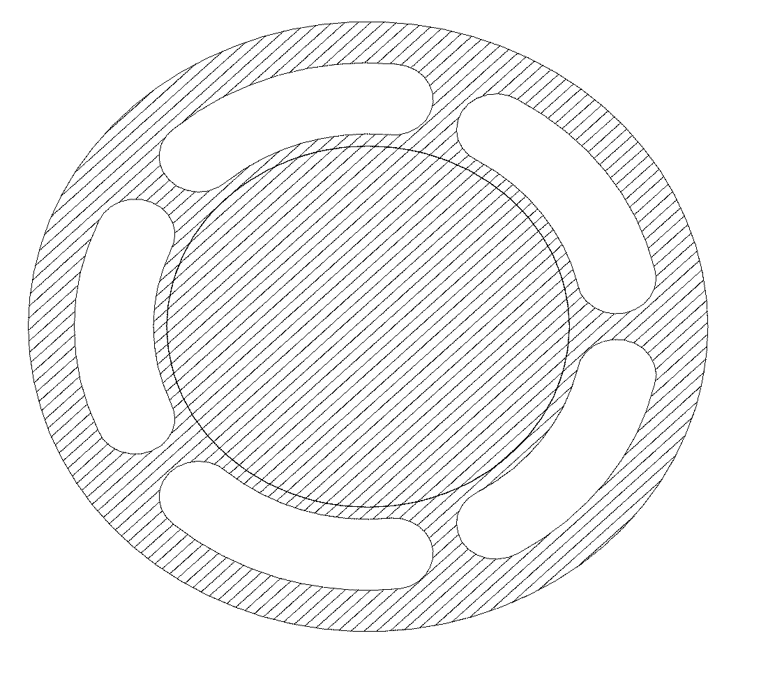
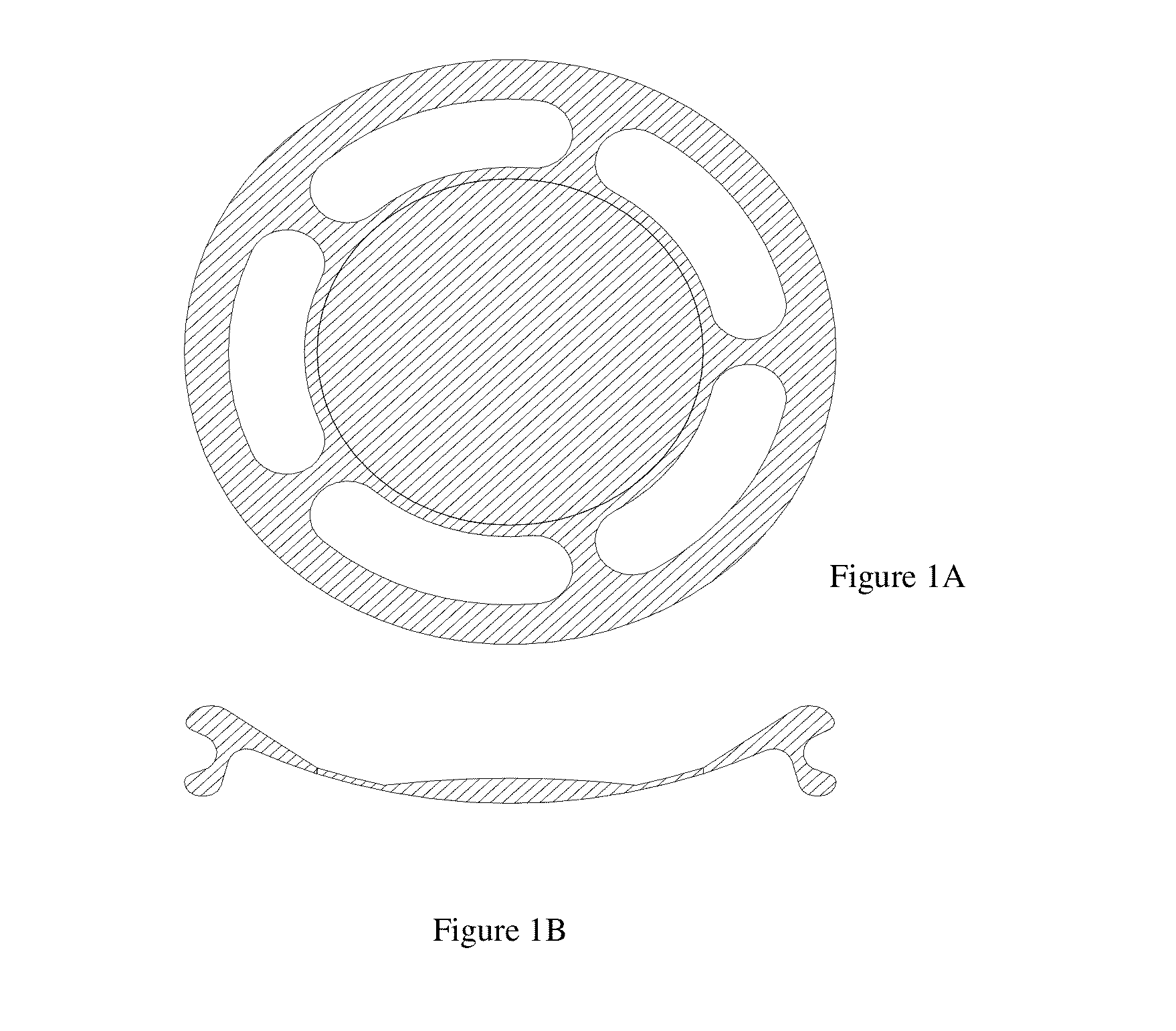
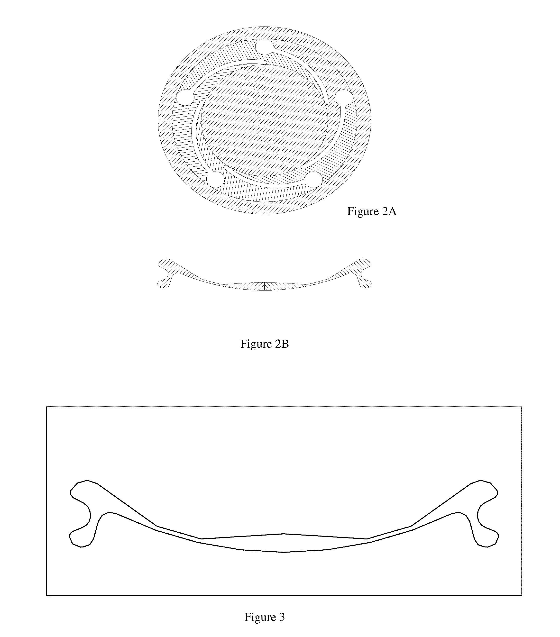
[0044]The haptic device is used to affix an intraocular lens within the lens capsule once the natural crystalline lens has been removed surgically. The three specific design purposes of the haptic are: i) to permit the lens to be implanted in the eye by means of an injector through an incision of less than about 3 mm; ii) to allow the lens to move within the posterior chamber of the eye in order to provide focal flexibility to the patient; and iii) to affix the lens in the lens capsule in such a way as to minimize the risk of Posterior Capsule Opacification (“PCO”), a negative consequence of lens replacement procedures that currently occurs in approximately 50% of patients within 2 to 3 years after surgery, iv) to maximize circulation of the aqueous humor within the lens capsule to minimize capsular fibrosis, and v) to provide a safe and comfortable framework for lenses with different styles of optics, with the objective of preserving as much as possible the natural physiognomy of t...


PUM


Abstract

A haptic for fixation to, and manufacture in conjunction with, an intraocular lens to be implanted in the natural lens capsule of the human eye is disclosed. The haptic secures the lens in an appropriate position within the natural capsule so as to provide optimal visual acuity through the aphakic lens. The haptic is designed to position the lens neutrally, anteriorly or posteriorly within the lens envelope. The haptic has an anterior retention ring and a posterior retention ring.

Description

REFERENCE TO RELATED APPLICATIONS[0001]This application is a continuation-in-part of U.S. Non-Provisional application Ser. No. 12 / 626,473 of the same title and filed Nov. 25, 2009, which claims priority to U.S. Provisional Application No. 61 / 118,085 of the same title and filed Nov. 26, 2008, U.S. Provisional Application No. 61 / 157,781 of the same title and filed Mar. 5, 2009, and U.S. Provisional Application No. 61 / 184,655 of the same title and filed Jun. 5, 2009. This application also claims priority to U.S. Application No. 62 / 028,375 of the same title, filed Jul. 24, 2014. Each application is specifically and entirely incorporated by reference.BACKGROUND[0002]1. Field of the Invention[0003]This invention is directed to haptic devices for intraocular lenses that provide increased comfort and performance to a patient. In particular, the invention is directed to haptic devices and designs, that consider a two-ring configuration within which the lens optic is held, that enhance post-s...

Claims


Application Information

Patent Timeline
IPC IPC(8): A61F2/16
CPCA61F2/1624A61F2/16A61F2002/16905A61F2002/169A61F2002/1682A61F2/1613
Inventor HAYES, ANNA S.
Owner ANEW IOL TECH
Why Eureka
Try Eureka