Haptic devices for intraocular lens

a technology of haptic devices and intraocular lenses, which is applied in the field of haptic devices for intraocular lenses, can solve the problems of minor distortion of the optics, reduced or eliminated eye's ability to change focus (accommodate), and will not return cataracts, so as to reduce the amount of clearance, prevent cell migration, and reduce the effect of cell migration

a technology of haptic devices and intraocular lenses, which is applied in the field of haptic devices for intraocular lenses, can solve the problems of minor distortion of the optics, reduced or eliminated eye's ability to change focus (accommodate), and will not return cataracts, so as to reduce the amount of clearance, prevent cell migration, and reduce the effect of cell migration

US9439755B2Active Publication Date: 2016-09-13ANEW IOL TECH

Image

  • Haptic devices for intraocular lens
  • Haptic devices for intraocular lens
  • Haptic devices for intraocular lens

Examples


examples

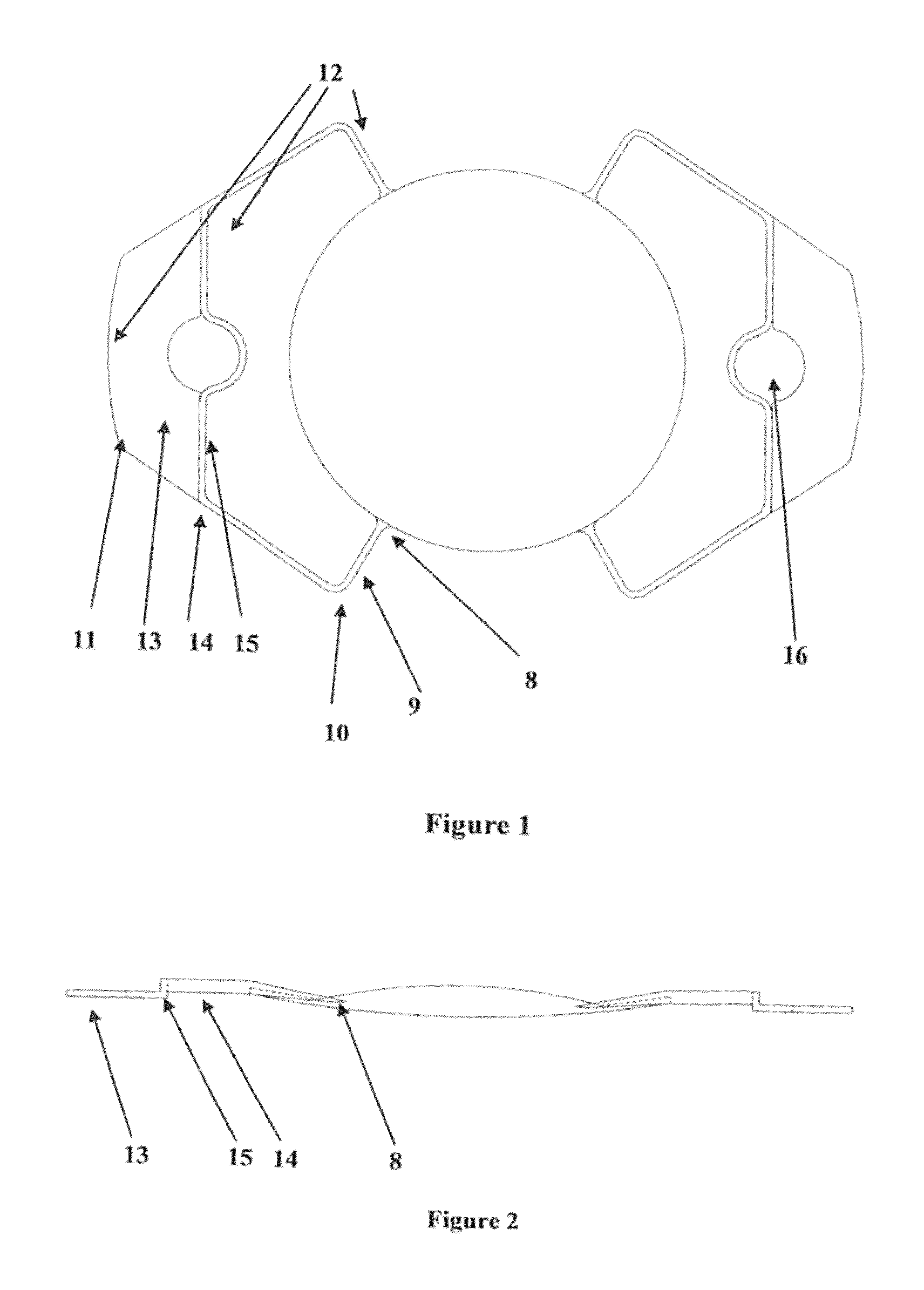
[0070]Depicted in FIG. 1 is a top view of an intraocular lens with a haptic device, and FIG. 2, a sagittal view. The haptic attachment point 8 to optic is shown along with a ribbon shaped haptic extension 9 which is in a plane through the center of the optic and the attachment point. The ribbon shaped haptic arm intersection with a circular plane larger than the radius of the optic. The solid end portion of the haptic 13 intersects the outside diameter of the lens at a point that is parallel to a plane passing through the 12 o'clock and 6 o'clock positions of the lens. The overall shape of the haptic resembles a kidney with sharper curves where the lens optic makes up a portion of the kidney. Solid end portion 13 of the haptic is thinner than the ribbon shaped sections 9.

[0071]As depicted in FIG. 1, ribbon shaped haptic 9 lies between the solid portion 13 and the end of the extended arm 8. The ribbon shaped section of the haptic 9 is shown above the solid portion of the haptic 13 in...


PUM


Abstract

The inventive is directed to a haptic for fixation to, and manufacture in conjunction with, an intraocular lens to be implanted in the natural lens capsule of the human eye. The haptic secures the lens in an appropriate position within the natural capsule so as to provide optimal visual acuity through the aphakic lens. The haptic ends are designed to position the lens neutrally, anteriorly or posteriorly within the lens envelope. At the connection point of the ribbon portion to the solid end plate of the haptic, the haptic may be notched to facilitate compressing the lens into its injector for insertion into the eye through an incision in the cornea. Once compressed and passed through the cornea, the implanted lens will be secured by the haptics in the lens capsule once all possible natural lens material and epithelial cells have been removed.

Description

REFERENCE TO RELATED APPLICATIONS[0001]This application claims priority to U.S. Provisional Application No. 61 / 118,085 of the same title and filed Nov. 26, 2008, U.S. Provisional Application No. 61 / 157,781 of the same title and filed Mar. 5, 2009, and U.S. Provisional Application No. 61 / 184,655 of the same title and filed Jun. 5, 2009, the entirety of each of which is hereby incorporated by reference.BACKGROUND[0002]1. Field of the Invention[0003]This invention is directed to haptic devices for intraocular lenses that provide increased comfort and performance to a patient. In particular, the invention is directed to haptic devices and designs, including injectors, for insertion of intraocular lenses without rolling the lenses, and to methods for performing insertion. Specifically, the invention, along with its various iterations, is designed to provide suitable degrees of focal flexibility, or accommodation, when used in conjunction with a monofocal optic, and, in certain instances,...

Claims


Application Information

Patent Timeline
13 Sep 2016
Publication
US9439755B2
IPC
A61F2/16
CPC
A61F2/1613; A61F2002/169; A61F2002/1681; A61F2002/1682
Inventors
CALLAHAN, WAYNE B.; KOCH, PAUL S.