Method and device for air-jet assisted center frame damping and adjusting steam turbine air seal

An auxiliary center, steam turbine technology, applied in mechanical equipment, engine components, machines/engines, etc., to achieve the effect of reducing steam leakage, maintaining stability, and reducing radial runout

Inactive Publication Date: 2019-03-08
HUADIAN ENERGY COMPANY LIMITED
View PDF4 Cites 0 Cited by
  • Summary
  • Abstract
  • Description
  • Claims
  • Application Information

AI Technical Summary

Problems solved by technology

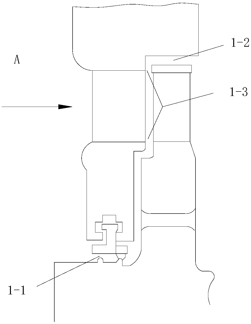
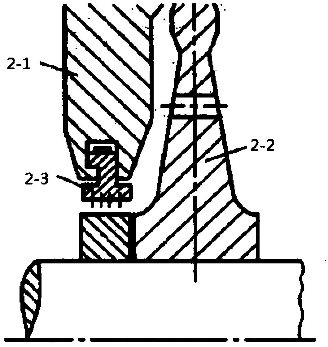
[0033] The purpose of the present invention is to solve the problem that in the prior art, when reducing the air leakage loss at the top air seal of the steam turbine blade, it only adopts a passive response to the radial runout of the rotor, which will bring other unfavorable factors while achieving a certain effect

Method used


Image

  • Method and device for air-jet assisted center frame damping and adjusting steam turbine air seal
  • Method and device for air-jet assisted center frame damping and adjusting steam turbine air seal
  • Method and device for air-jet assisted center frame damping and adjusting steam turbine air seal

Examples


specific Embodiment approach 1

[0045] Specific implementation mode one: the following combination Figure 6 to Figure 10 This embodiment will be specifically described. This implementation mode is realized through the following steps:

[0046] 1. Start the steam turbine; before starting, the gap t between the surface of the inner hole of the air seal assembly at the top of the moving blade of the steam turbine and the outer surface of the turbine blade is between 1.5 and 10 mm;

[0047] 2. After the steam turbine reaches the normal speed, adjust the auxiliary support assembly arranged at the inner hole of the diaphragm, so that the upper and lower bearing pads on the auxiliary support assembly gradually close together and surround the main shaft of the steam turbine to reduce the radial runout of the main shaft of the steam turbine ; In the initial state, the distance between the inner surface of the upper bearing bush 7-1 and the lower bearing bush 7-2 on the auxiliary support assembly and the surface of ...

specific Embodiment approach 2

[0057] Specific implementation mode two: the following combination Image 6 and Figure 8 This embodiment will be specifically described. This embodiment is compared with Embodiment 1: this method also includes three groups of distance sensors 6-14 and a group of vibration sensors 8-5, and the first group of distance sensors 6-14 is arranged on the air seal body 6-11 to Real-time measurement of the gap between the gas seal body 6-11 and the outer surface of the steam turbine blade 6-12 and the radial runout of the outer surface of the steam turbine blade 6-12; the second group of distance sensors 8-4 are respectively arranged on the push rod 8-2 At the front end, the distance between the roller 8-1 and the steam turbine main shaft 9-3 and the radial runout of the steam turbine main shaft 9-3 are measured in real time; the third group of distance sensors is arranged on the upper bearing bush 7-1 and the lower bearing bush 7-2 , to measure the gap between the upper bearing bus...

specific Embodiment approach 3

[0061] Specific implementation mode three: the following combination Image 6 This embodiment will be specifically described. The fifth step of this embodiment also includes the following technical means. During the process of making the surface of the inner hole of the air seal assembly at the top of the moving blade close to the outer surface of the steam turbine blade 6-12, the air seal body 6-11 and the steam turbine blade 6 are collected in real time. -12 The gap on the outer surface and the radial runout on the outer surface of the steam turbine blade 6-12 and the vibration data collected by the vibration sensor 8-5, to ensure that the value of the gap t is always greater than the value of the radial runout, if the vibration data increases abnormally , then immediately reverse the action to increase the distance between the surface of the inner hole of the air seal assembly at the top of the rotor blade and the outer surface of the turbine blade, and resume operation whe...


PUM


Abstract

The invention provides a method and a device for adjusting an air seal of a steam turbine through air injection assisting center frame vibration reduction and relates to a method and a device for adjusting an air seal gap at the top of a movable vane of the steam turbine and solves the problem that other negative factors can be caused by the fact that radial run-out of a rotor is only handled passively when air leakage loss in the top air sealing position of the movable vane of the steam turbine is reduced at present. The scheme of the method and the device is that after the steam turbine reaches normal rotating speed, an upper bearing and a lower bearing surround a spindle of the steam turbine gradually to reduce radial run-out of the spindle of the steam turbine; then three rollers approach the spindle of the steam turbine gradually, and after each roller makes contact with the spindle of the steam turbine, each roller and the spindle of the steam turbine are in linear contact in an opposite rolling manner; the upper bearing and the lower bearing gradually retreat to get away from the spindle of the steam turbine; finally, the inner hole surface of an air seal assembly at the top of the movable vane is closed gradually towards the outer diameter of a blade of the steam turbine, and the finally formed gap between the inner hole surface and the outer diameter ranges from 0.15 mm to 0.25 mm; an air injection bearing is further adopted to restrain the spindle of the steam turbine, and an adjusting process is more stable.

Description

technical field [0001] The invention relates to a method and a device for adjusting the air seal gap at the top of a steam turbine blade. Background technique [0002] A steam turbine is a power machine that converts the thermal energy of steam into mechanical energy. The stage is its most basic working unit. Structurally, each stage is composed of a nozzle and a moving blade cascade. After the steam enters the nozzle, its thermal energy is converted into Kinetic energy then enters the rotor blades, giving impact to the rotor blades, causing the impeller to rotate and output mechanical work. [0003] A large steam turbine is composed of multiple stages, and each stage is composed of dynamic and static parts, so the whole steam turbine is also composed of dynamic and static parts. There must be a certain gap between the rotating and stationary parts of the steam turbine to prevent mutual friction. Since there is a pressure difference between the inside and outside of the cy...

Claims


Application Information

Patent Timeline
Patent Type & Authority Patents(China)
IPC IPC(8): F01D25/28F01D11/20F01D25/04
CPCF01D11/20F01D25/04F01D25/28
Inventor 常立宏刘翔太邵松林
Owner HUADIAN ENERGY COMPANY LIMITED
Why Eureka
Try Eureka