Latch mechanism

Pending Publication Date: 2015-11-19
CENT DESIGN
View PDF42 Cites 20 Cited by
  • Summary
  • Abstract
  • Description
  • Claims
  • Application Information

AI Technical Summary

Benefits of technology

The patent text describes a door or window controller that includes a tension adjustment mechanism or locking mechanism. The tension adjustment mechanism can simultaneously adjust the tension in each linkage member associated with the controller. The locking mechanism prevents accidental disengagement of the door or window and ensures that the second members are retained in their positions when the locking mechanism is locked. The magnetic attraction between the first and second members ensures that the latch mechanism automatically moves into a latched position when the door or window is closed and properly aligned within the frame. The security and operating convenience of the door or window are improved.

Problems solved by technology

One drawback with conventional bifold doors or windows is that individually operating each latch bolt or manually operating a lever handle on each door or window panel can be inconvenient and time consuming.
Moreover, it is easy for the user to inadvertently leave one or more latch bolts or panels unlocked.
If this occurs, the door or window may be blown open in windy conditions.
Further, a failure to properly latch the bifold door or window increases the ease with which burglars can enter a building through the unlatched door or window.

Method used


Image

  • Latch mechanism
  • Latch mechanism
  • Latch mechanism

Examples


Embodiment Construction

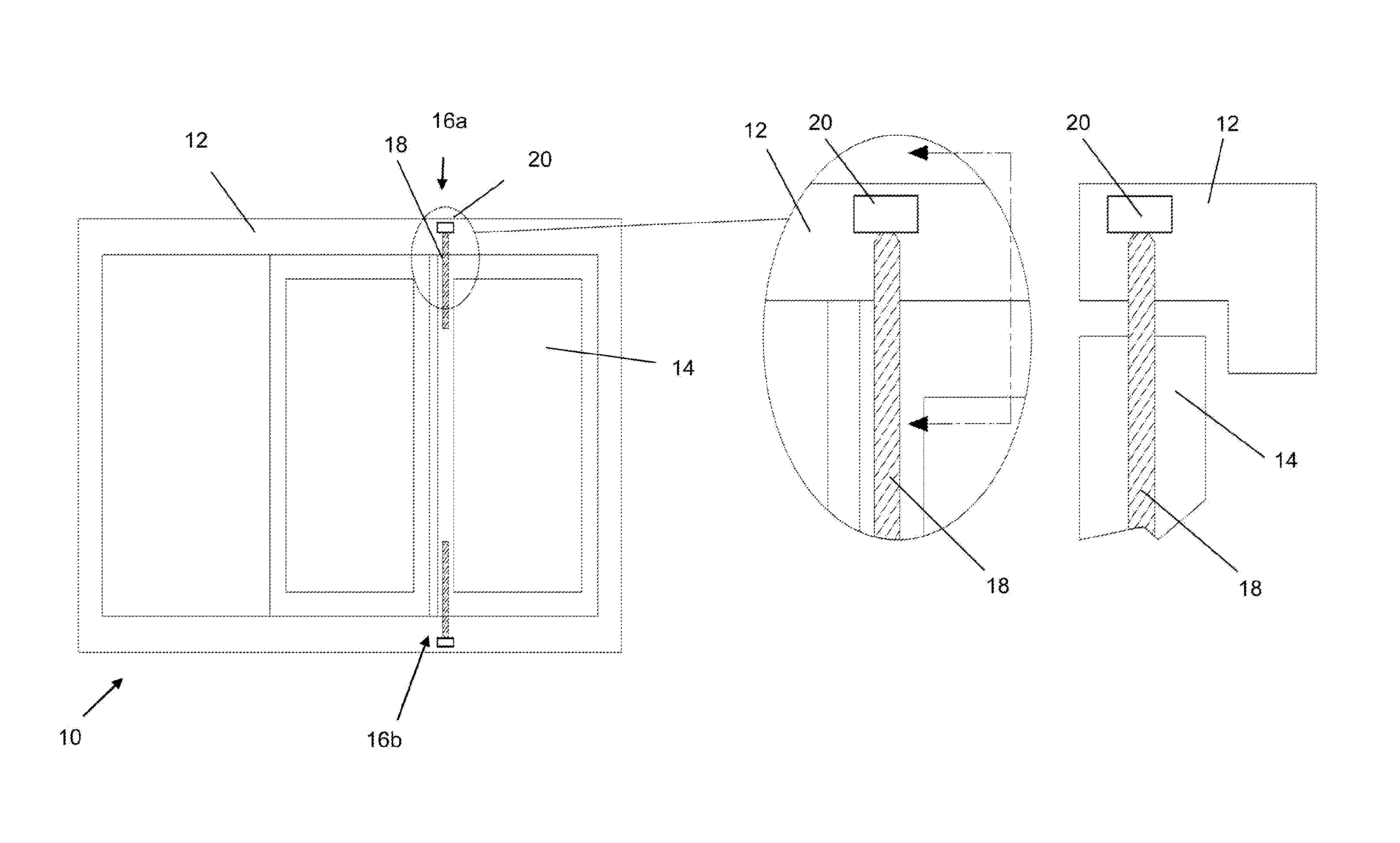
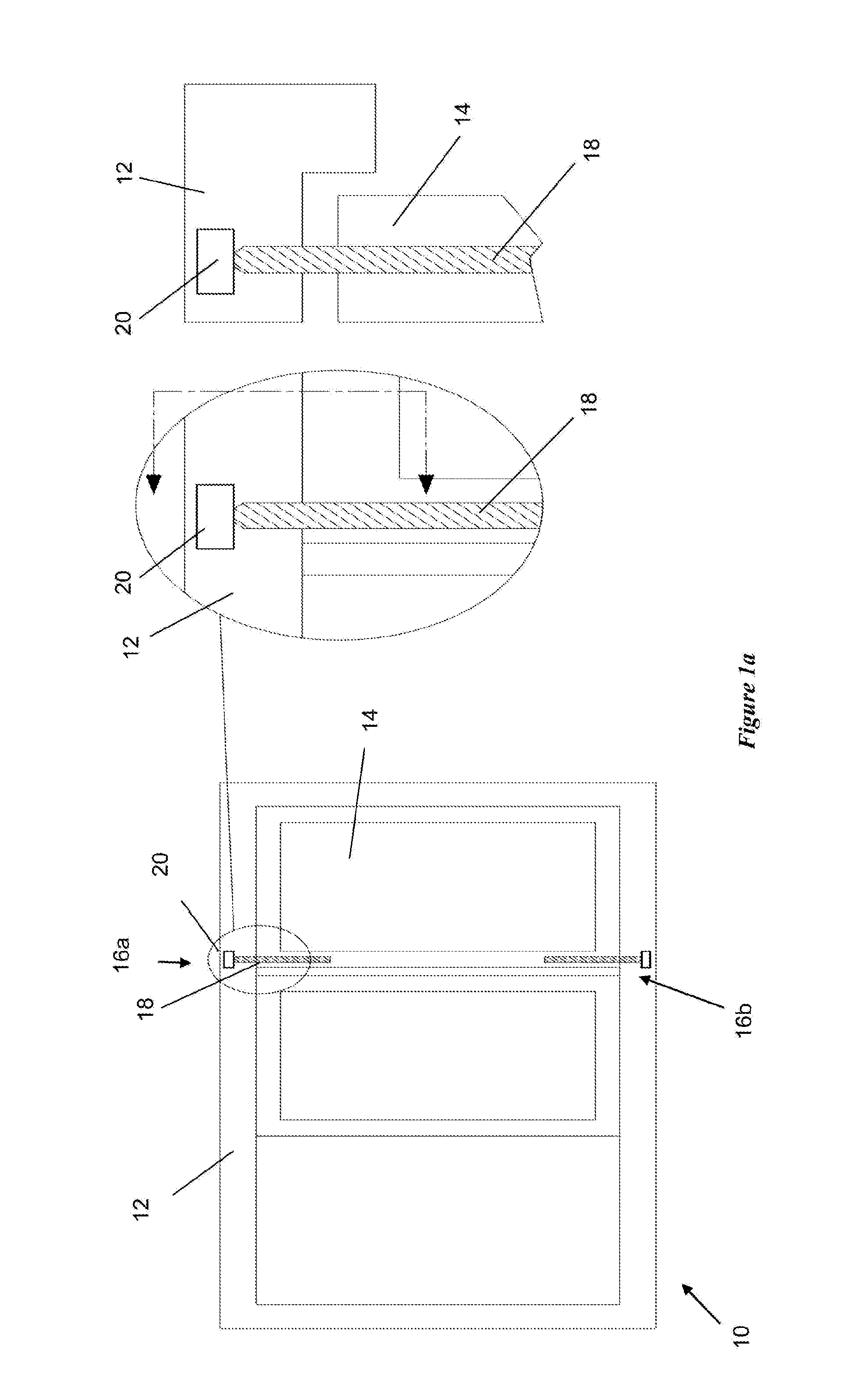
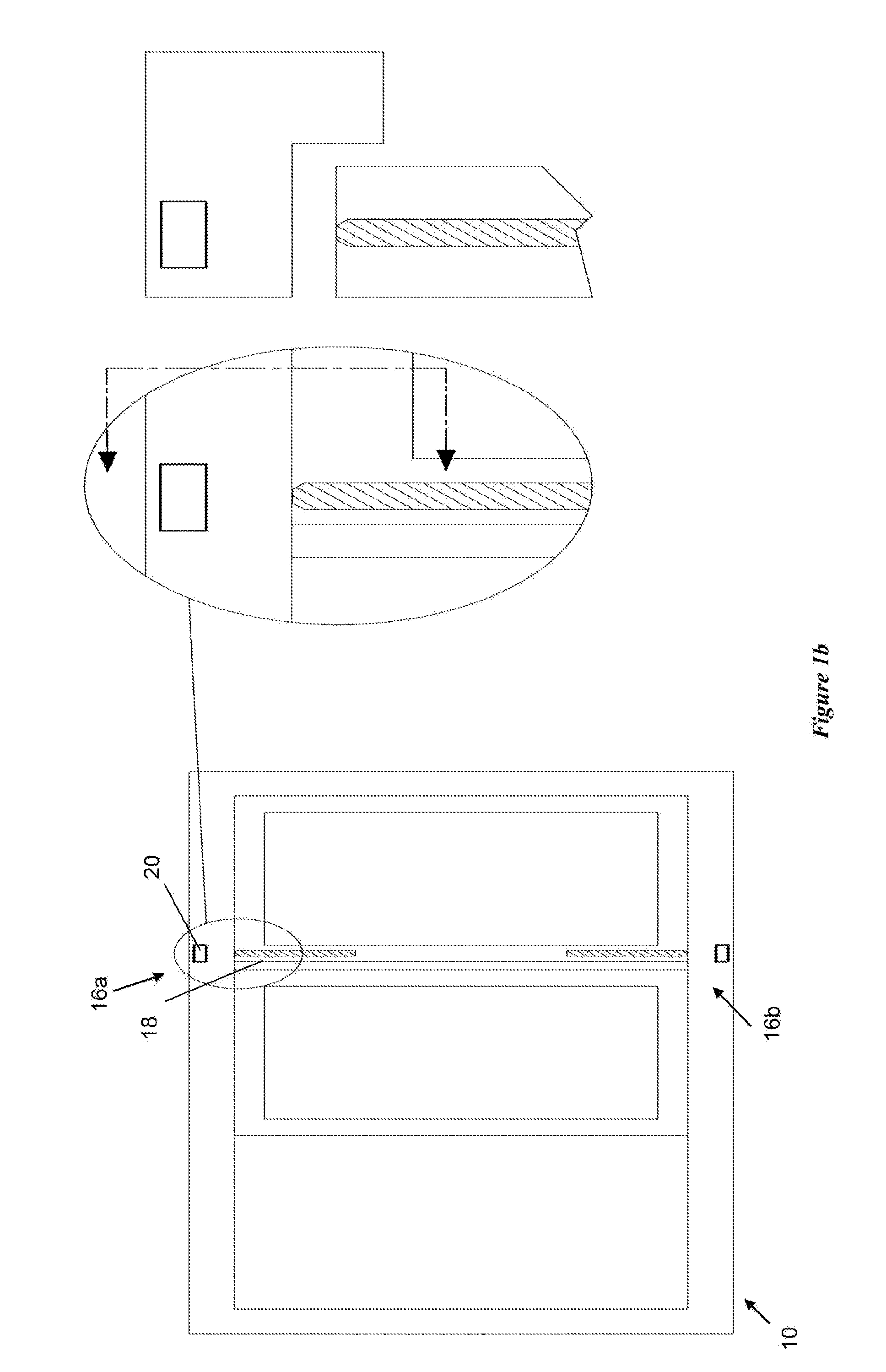
[0076]FIG. 1a illustrates a bifold door 10 having three door panels (only two shown) attached to a bifold door frame 12. One of the door panels 14 has two latch mechanisms 16a, 16b. One latch mechanism 16a is mounted proximate a top left corner of the door panel 14, and the other latch mechanism 16b is mounted proximate a bottom left corner of the door panel 14.

[0077]Each latch mechanism 16a, 16b includes a magnetic bolt 18 mounted in the door panel 14 and a ferromagnetic block 20 mounted in the door frame 12. The door frame 12 defines a channel opening (not shown) directly below the ferromagnetic block 20 to allow magnetic engagement between the magnetic bolt 18 and the ferromagnetic block 20 when the latch mechanism 16 in the latched position as shown in FIG. 1a.

[0078]When each latch mechanism 16a, 16b is in its latched position as shown in FIG. 1a, the respective magnetic bolt 18 is held within the respective channel opening of the door frame 12 so as to prevent movement of the ...


PUM


Abstract

The present invention is directed to a latch mechanism for latching a door or window panel to a frame. The latch mechanism includes: a pair of first members, a first of the pair of first members being located in an upper region of either the door or window panel or the frame, and a second of the pair of first members being located in a lower region of either the door or window panel or the frame and a pair of second members, a first of the pair of second members being located in an upper region of the other of the door or window panel or the frame to the first of the pair of first members and a second of the pair of second members being located in a lower region of the other of the door or window panel or the frame to the second of the pair first members the second members being movable between an unlatched position and a latched position wherein the second members are brought into abutment with, or close proximity to, the respective first members, wherein the first members are adapted to move from the unlatched position to the latched position under a magnetic attraction to the respective second members when the door or window panel is brought into a closed condition and wherein the second members are coupled to a controller via one or more linkage members, wherein actuation of the controller results in moving the second members from the latched position to the unlatched position.

Description

TECHNICAL FIELD[0001]The present invention relates to a latch mechanism for a door or window panel. In particular, the invention is directed to a latch mechanism associated with a bifold door or window panel and assembly, although the scope of the invention is not necessarily limited thereto.BACKGROUND ART[0002]Conventionally, bifold door or window panels are secured against horizontal members of a door or window frame via latch bolts at an upper and / or lower end of the door panel. A user is typically required to individually unlock each latch bolt before opening the door or window. Similarly, when securing the door or window in a closed position, the user is required to individually lock each latch bolt to securely lock the door or window.[0003]Some bifold door or window panels use twin-point latch bolts (i.e. latch bolts configured at the upper and lower ends of the door or window panel) connected to a common central lever handle. The lever handle is used to manually move the twin...

Claims


Application Information

Patent Timeline
IPC IPC(8): E05C19/16E05C9/04
CPCE05C19/163Y10T292/0834E05C9/04E05B53/003E05B65/0085E05C19/168E05B47/004E05B63/20E05C9/00Y10S292/36Y10T292/11
Inventor MA, MATTHEWPACHOLKE, GLENSPORK, NIGELCOOKSLEY, ANDREW
Owner CENT DESIGN
Why Eureka
Try Eureka