
Nonlinear model-based controller for premixed charge compression ignition combustion timing in diesel engines

a technology of ignition combustion timing and model-based controller, which is applied in the direction of electric control, machines/engines, output power, etc., can solve the problems of limited widespread adoption of diesel pcci and other advanced combustion modes, the true cost of their use is the increase in fuel consumption, and the lack of direct combustion triggers

Active Publication Date: 2015-11-19
PURDUE RES FOUND INC
View PDF9 Cites 30 Cited by
  • Summary
  • Abstract
  • Description
  • Claims
  • Application Information

AI Technical Summary

Benefits of technology

This patent describes a method for controlling the start of combustion in a diesel engine using a closed-loop controller that takes into account oxygen fraction dynamics. This method can help reduce NOx and PM emissions from conventional diesel combustion. While the patent describes various methods for controlling the combustion phasing of PCCI, the main technical effect of this patent is the use of a nonlinear model-based closed-loop controller that includes a PCCI combustion timing model. This model can be particularly useful for engines that have flexible intake valve actuation. Overall, this patent provides a way to optimize engine performance and reduce emissions through advanced combustion control.

Problems solved by technology

While the after treatment systems are effective in reducing emissions, the true cost of their usage is the increase in fuel consumption required.
The lack of a direct combustion trigger has previously limited the widespread adoption of diesel PCCI and other advanced combustion modes.
The nonlinear relationships between the control inputs and the combustion system response can limit the effectiveness of traditional, non-model-based controllers.

Method used


Image

  • Nonlinear model-based controller for premixed charge compression ignition combustion timing in diesel engines
  • Nonlinear model-based controller for premixed charge compression ignition combustion timing in diesel engines
  • Nonlinear model-based controller for premixed charge compression ignition combustion timing in diesel engines

Examples


Embodiment Construction

[0040]For the purposes of promoting an understanding of the principles of the invention, reference will now be made to the embodiments illustrated in the drawings and specific language will be used to describe the same. It will nevertheless be understood that no limitation of the scope of the invention is thereby intended, such alterations and further modifications in the illustrated device, and such further applications of the principles of the invention as illustrated therein being contemplated as would normally occur to one skilled in the art to which the invention relates. At least one embodiment of the present invention will be described and shown, and this application may show and / or describe other embodiments of the present invention. It is understood that any reference to “the invention” is a reference to an embodiment of a family of inventions, with no single embodiment including an apparatus, process, or composition that should be included in all embodiments, unless otherw...


PUM


Abstract

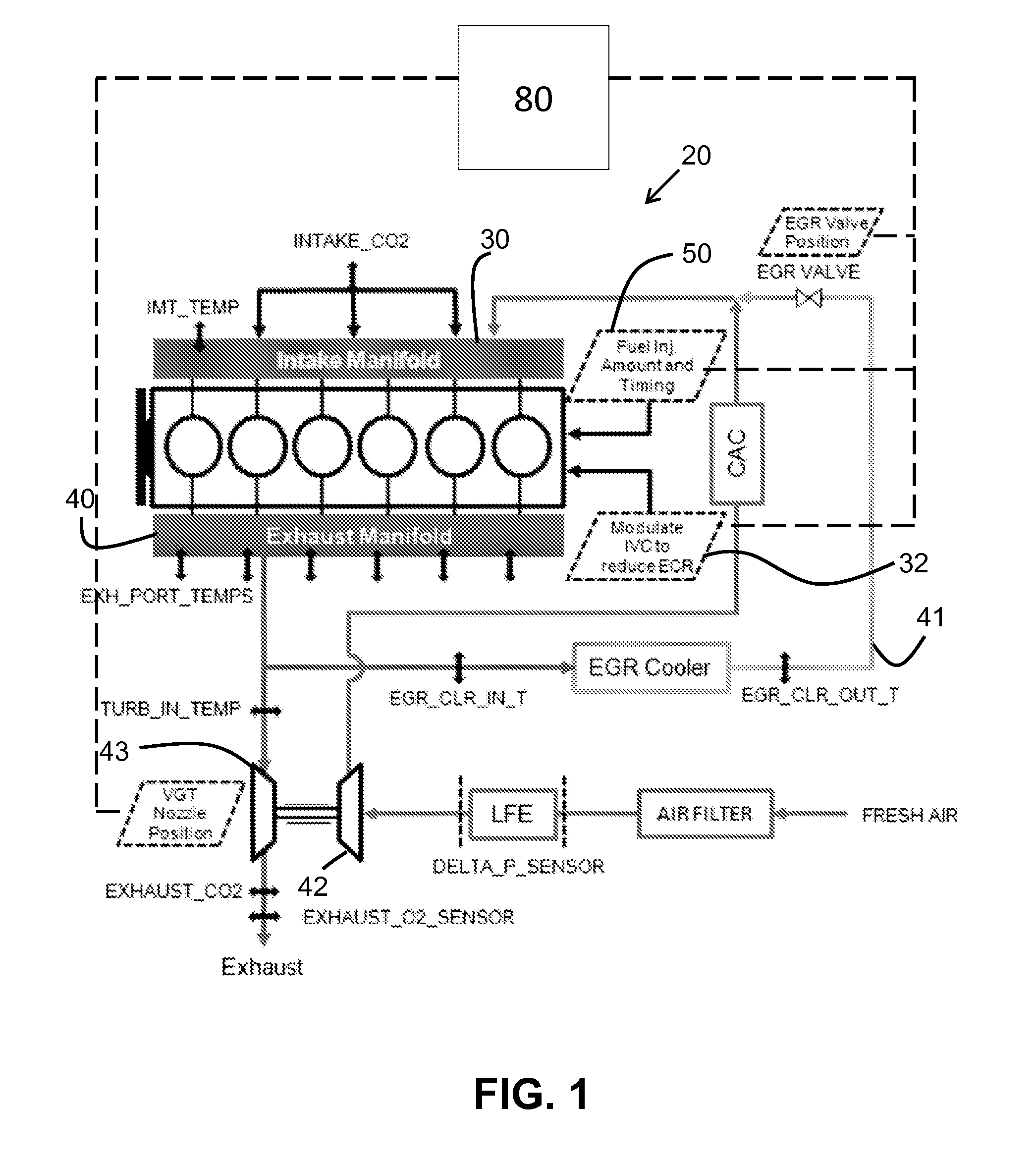
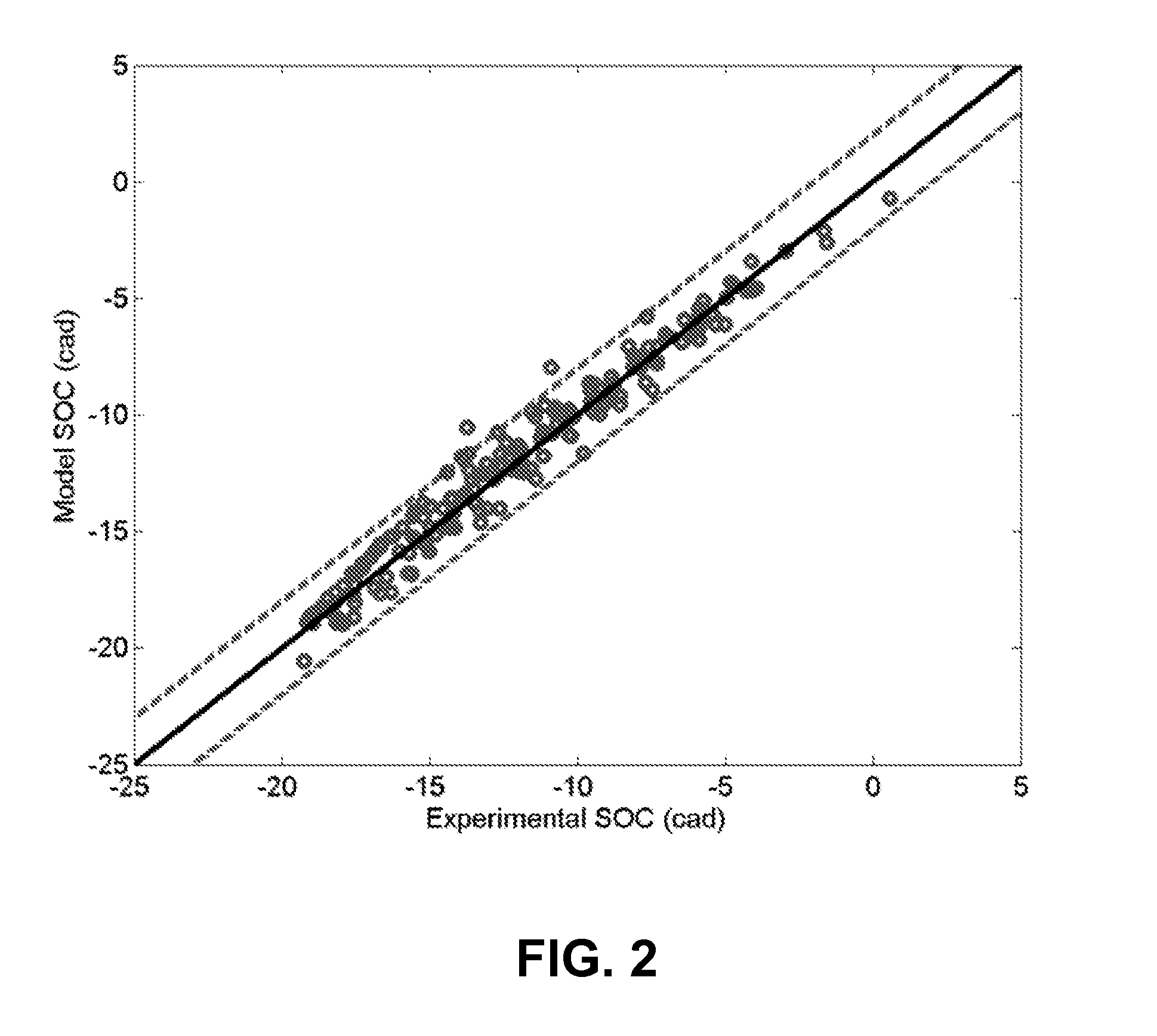
Advanced combustion modes, such as PCCI, operate near the system stability limits. In PCCI, the combustion event begins without a direct combustion trigger in contrast to traditional spark-ignited gasoline engines and direct-injected diesel engines. The lack of a direct combustion trigger encourages the usage of model-based controls to provide robust control of the combustion phasing. The nonlinear relationships between the control inputs and the combustion system response often limit the effectiveness of traditional, non-model-based controllers. Accurate knowledge of the system states and inputs is helpful for implementation of an effective nonlinear controller. A nonlinear controller is developed and implemented to control the engine combustion timing during diesel PCCI operation by targeting desired values of the in-cylinder oxygen concentration, pressure, and temperature during early fuel injection.

Description

CROSS REFERENCE TO RELATED APPLICATION[0001]This application claims the benefit of priority to U.S. Provisional Patent Application Ser. No. 61 / 736,346, filed Dec. 12, 2012, and U.S. Provisional Patent Application Ser. No. 61 / 784,204, filed Mar. 14, 2013, all of which are incorporated herein by reference.GOVERNMENT RIGHTS[0002]This invention was made with government support under DE-EE0003403 awarded by Department of Energy. The government has certain rights in the invention.BACKGROUND OF THE INVENTION[0003]Engine developers continually balance the tightening emissions legislation with consumer demands for maximum fuel efficiency. In modern diesel engines, after treatment systems are deployed to reduce the engine-out emissions to the legislated tailpipe-out levels. While the after treatment systems are effective in reducing emissions, the true cost of their usage is the increase in fuel consumption required.[0004]Advanced combustion modes including diesel premixed charge compression ...

Claims


Application Information

Patent Timeline
IPC IPC(8): F02D41/30F02D41/40F02D41/00F02B1/12F02D13/02
CPCF02D41/3035F02B1/12F02D41/401F02D41/0007F02D41/0062F02D13/0226F02D13/0265F02D35/02F02D41/0072F02D41/1401F02D41/1447F02D41/1458F02D2041/1415F02D2041/1416F02D2041/1433F02D2200/0402F02D2200/0406F02D2200/0411F02D2200/0414F02M26/05F02M26/10F02M26/23Y02T10/12Y02T10/40
Inventor SHAVER, GREGORY M.KOCHER, LYLE E.HALL, CARRIEVAN ALSTINE, DANIELMAGEE, MARK
Owner PURDUE RES FOUND INC
Learn More