
Method and System for Identifying Leaks in Fluid Pipe Construction

a technology of fluid pipe and leak detection, applied in the direction of fluid tightness measurement, instruments, machines/engines, etc., can solve the problem that the solution cannot be used to detect real-time fluid leakage in the pipe construction

Inactive Publication Date: 2015-11-19
TRIPLE PLUS
View PDF6 Cites 19 Cited by
  • Summary
  • Abstract
  • Description
  • Claims
  • Application Information

AI Technical Summary

Benefits of technology

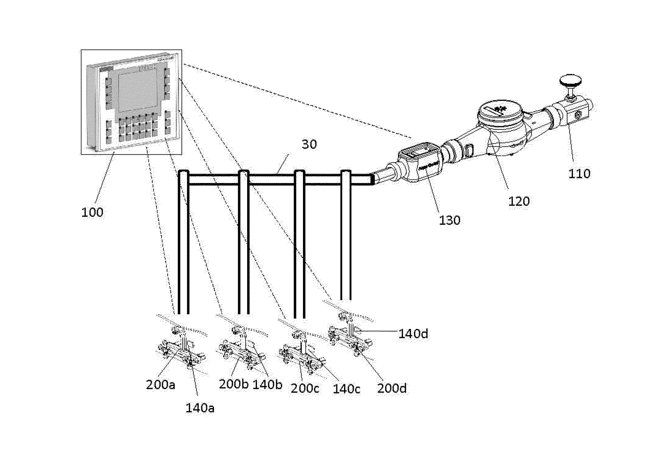
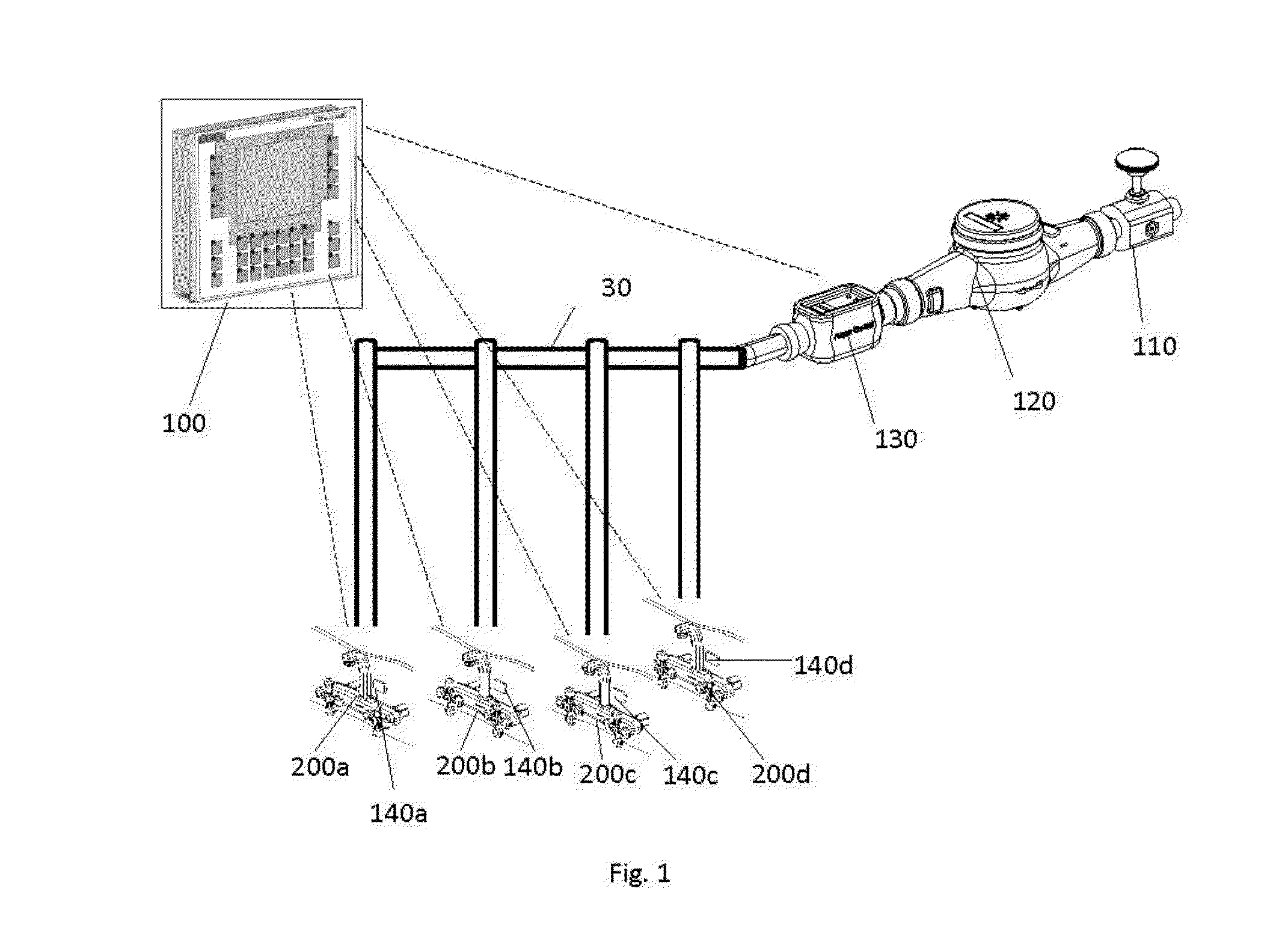
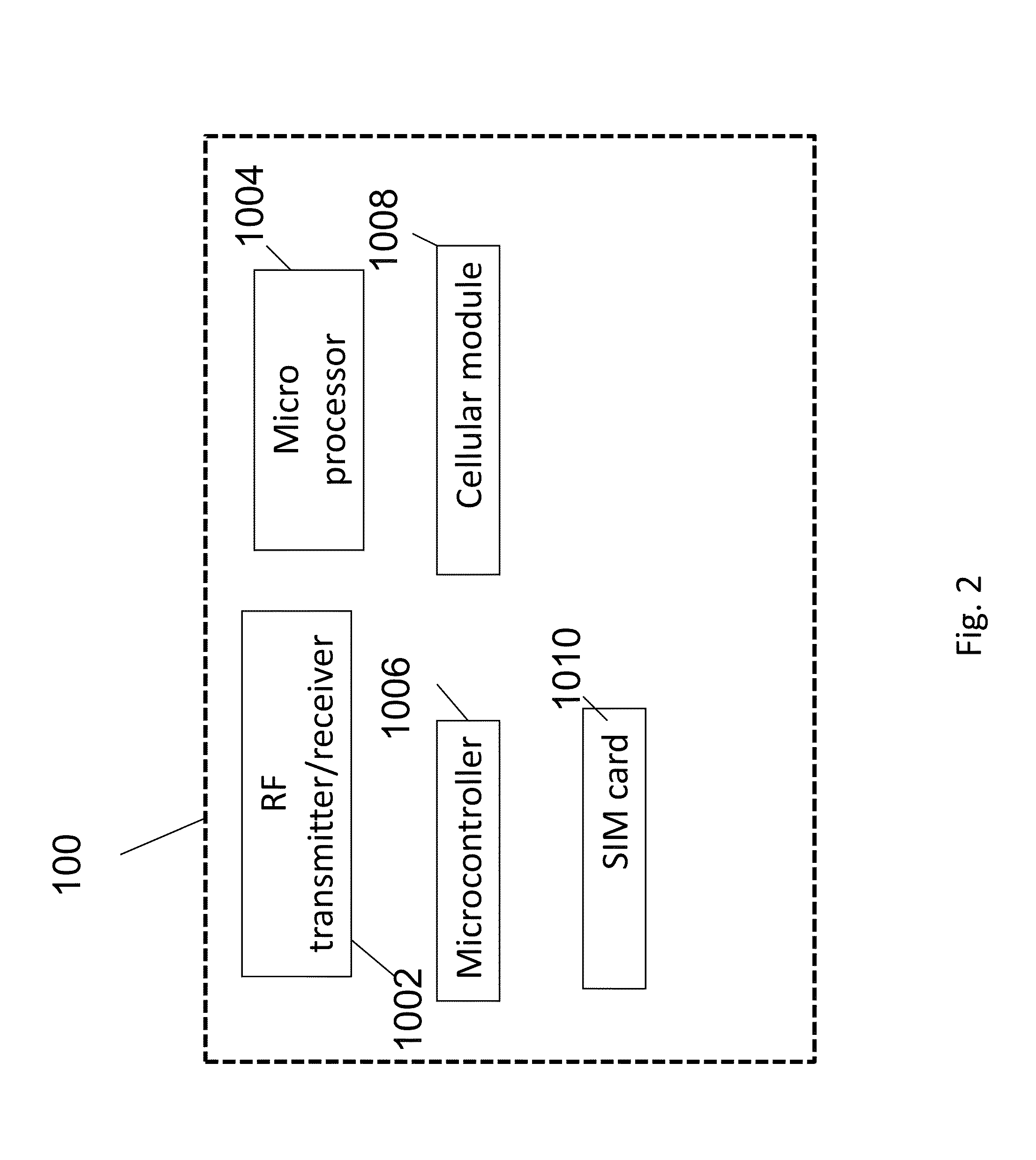
The present invention provides a method and system for identifying defects in fluid pipe constructions using acoustic sensors placed at the entrance and exit points of the pipe. The method involves processing the received output signal data of the sensors to identify flow-related defects by calculating the difference between the flow in the entrance and exit points of the pipe construction within the ultrasonic spectral range and comparing it with references indicating different flow states. The system includes at least two acoustic sensors, a processing unit, and a detection unit and electronically controlled shutoff unit for identifying and controlling flow defects in real-time. The system can also use non-acoustic sensors for flow measurement and can output and transmit alerts upon identifying a flow defect. The technical effects of the invention include improved efficiency in identifying defects in fluid pipe constructions and improved operational efficiency in managing flow-related issues.

Problems solved by technology

The various leak detection methods described above use acoustic sensors located within the pipes, requiring complicated algorithm for identifying leak along the pipe, such solution may not be used to detect real time fluid leak within pipe construction for immediate activation of shutoff valve.

Method used


Image

  • Method and System for Identifying Leaks in Fluid Pipe Construction
  • Method and System for Identifying Leaks in Fluid Pipe Construction
  • Method and System for Identifying Leaks in Fluid Pipe Construction

Examples


example 1

Water Flow Detection in Valves and Taps Using Binary Hypothesis Decision for Leakage Monitoring

1 Feasibility Study Using Professional Audio Equipment

1.1 Establish Measuring System

[0077]A measurement system was established using the high quality acoustic measurement equipment[0078]1. a tap,[0079]2. Brüel & Kjær 4942—½-inch diffuse-field microphone, 6 Hz to 16 kHz, prepolarized,[0080]3. Brüel & Kjær NEXUS 2690 Conditioning Amplifier,[0081]4. U24XL ESI audio—24-bit USB Audio Interface, and[0082]5. Laptop with MATLAB.

1.2 Perform Initial Measurements

[0083]Measurements were taken for different positioning of the microphone with respect to the tap:[0084]1. right on the tap,[0085]2. at a distance of 0.3 m away from the tap and adjacent to the wall behind the tap, and[0086]3. at a distance of 1.5 m away from the tap and adjacent to a wall in the room.

[0087]The microphone acoustic sensor was either coupled over the tap, located 0.3 meters away from the tap, and is located 1.5 meters away fro...


PUM


Abstract

System and method for identifying defects in a fluid pipe construction, where the method includes: receiving output signal data of at least two acoustic sensors configured for measuring flow related acoustic measures of the pipe constructions at least at the entrance point and at least one exit points thereof; and processing the received output signal data for identifying one or more types of flow related defects, using ultrasonic spectral range of the received signal data, wherein the identification is carried out by calculating at least the difference between the flow in the entrance and exit points of the pipe construction within the ultrasonic spectral range and comparing the calculated difference with at least two references indicating at least two flow states. The references are indicative of the flow states within the ultrasonic spectral range under normal conditions.

Description

CROSS-REFERENCE TO RELATED PATENT APPLICATIONS[0001]This application is a continuation in part (CIP) of U.S. patent application Ser. No. 13 / 108,288 (publication no. US 2012 / 02965802 A1) filed on May 16, 2011, which is incorporated herein by reference in its entirety.FIELD OF THE INVENTION[0002]The present invention relates to the field of identification of flow of fluid in pipes construction and more specifically to identification of leaks in pipe construction using acoustical sensors.BACKGROUND OF THE INVENTION[0003]There are various known in the art systems for leak detection:[0004]US application No. 2006174707 discloses a device for detecting and controlling abnormal flow occurrences in a liquid or gas-carrying infrastructure using acoustics sensors.[0005]U.S. Pat. No. 5,040,409 discloses an acoustic sensor used to determine when a leak occurs in a sprinkling system. When a catastrophic leak is detected, an alarm signal is generated and a shutoff valve may be actuated in order to...

Claims


Application Information

Patent Timeline
IPC IPC(8): G01M3/24G16Z99/00
CPCG01M3/243F17D5/06F17D5/005G16Z99/00
Inventor DOTAN, OMRIMARGALIT, SHAULBARKAY, DOV
Owner TRIPLE PLUS
Learn More