
Restraint Device

a technology for restraining devices and vehicles, which is applied in the direction of instruments, structural/machine measurement, transportation and packaging, etc., can solve the problems of chain and/or belts having several problems, chain and/or belts posing a risk of scratching the truck, and repair scratches, etc., to achieve safe restraint of trucks and reduce labor costs

Active Publication Date: 2015-11-19
HEMERSON ALBERT
View PDF8 Cites 4 Cited by
  • Summary
  • Abstract
  • Description
  • Claims
  • Application Information

AI Technical Summary

Benefits of technology

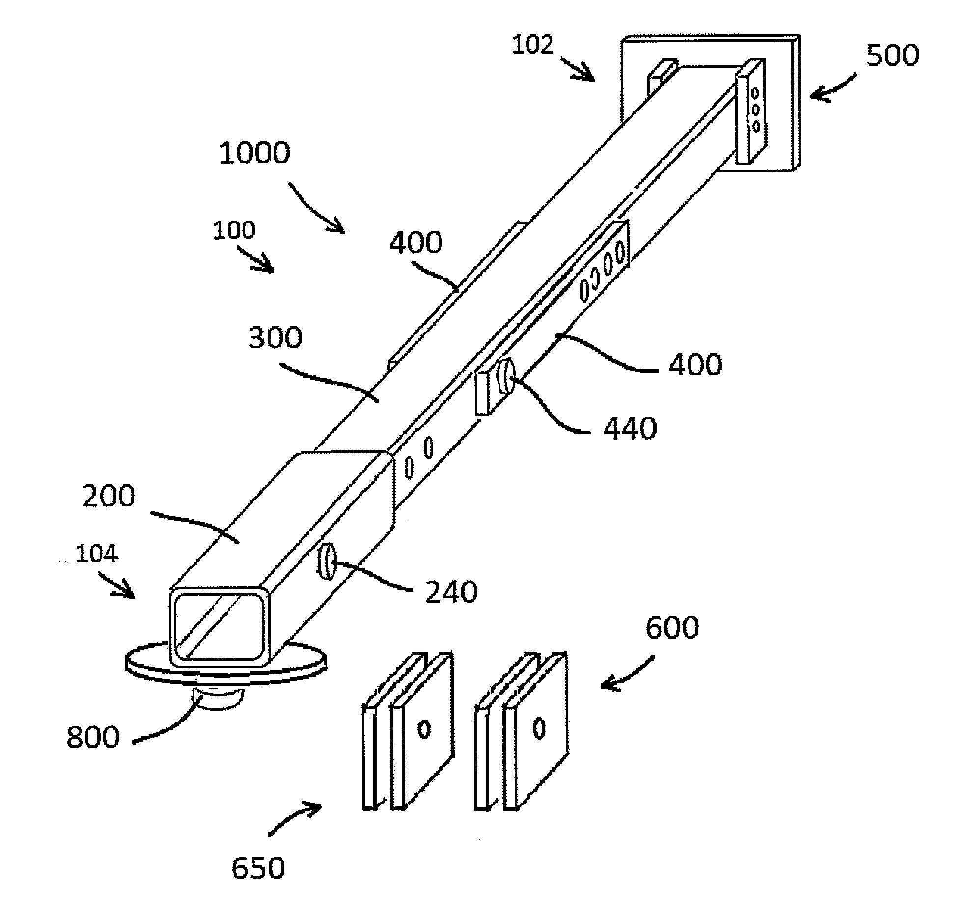
The patent is about a new device and method for safely restraining a truck during a dyno test. The inventors noticed that chains and belts had many problems, including scratching the truck, being time-consuming to attach, and potentially causing damage or loss of life if they break. As a result, they created a new device that solves these issues. The device attaches to the Fifth Wheel of the truck and uses a boom and connecting structure to secure the truck during the test. The technical effects are that it provides a safer way to restrain the truck, reduces the risk of damage to the truck and other components, and reduces the risk of injury to operators and potential loss of life.

Problems solved by technology

The inventors have noticed that while chains and / or belts do a sufficient job at restraining a truck during a dyno test, the chains and / or belts have several problems.
First, the chains and / or belts pose of risk of scratching the truck while they are being attached to the truck and while the dyno test is running.
If parts are not removed from the truck and the parts are scratched by the belts and / or chains, the owner must either repair the scratches, the cost of which may be quite expensive, or simply “live with” the damage.
Additionally, attaching the belts and chains to the truck is a relatively time consuming process for a dyno operator.
Finally, the inventors note that while chains and / or belts sufficiently restrain the a truck during a dyno test, there is a risk of the belts and / or chains breaking.
Given the high rate at which the trucks tires spin during a dyno test, a broken belt and / or chain could have catastrophic results resulting in damage to the dyno, the truck, and potentially causing loss of human life.

Method used


Image

  • Restraint Device
  • Restraint Device
  • Restraint Device

Examples


Embodiment Construction

[0024]Example embodiments will now be described more fully with reference to the accompanying drawings, in which example embodiments of the invention are shown. The invention may, however, be embodied in different forms and should not be construed as limited to the example embodiments set forth herein. Rather, these example embodiments are provided so that this disclosure will be thorough and complete, and will fully convey the scope of the invention to those skilled in the art. In the drawings, the sizes of components may be exaggerated for clarity.

[0025]In this application, it is understood that when an element or layer is referred to as being “on,”“attached to,”“connected to,” or “coupled to” another element or layer, it can be directly on, directly attached to, directly connected to, or directly coupled to the other element or layer or intervening elements that may be present. In contrast, when an element is referred to as being “directly on,”“directly attached to,”“directly con...


PUM


Abstract

Disclosed is a method of testing a vehicle having a fifth wheel and an apparatus for restraining the vehicle. The method of testing the vehicle may include moving the vehicle on a dynamometer and inserting a coupling structure into the fifth wheel to secure the vehicle during a test. In accordance with example embodiments, the apparatus may include a boom having a pin connection and a connecting structure arranged at an end of the boom, the connecting structure being configured to couple to the fifth wheel of the vehicle.

Description

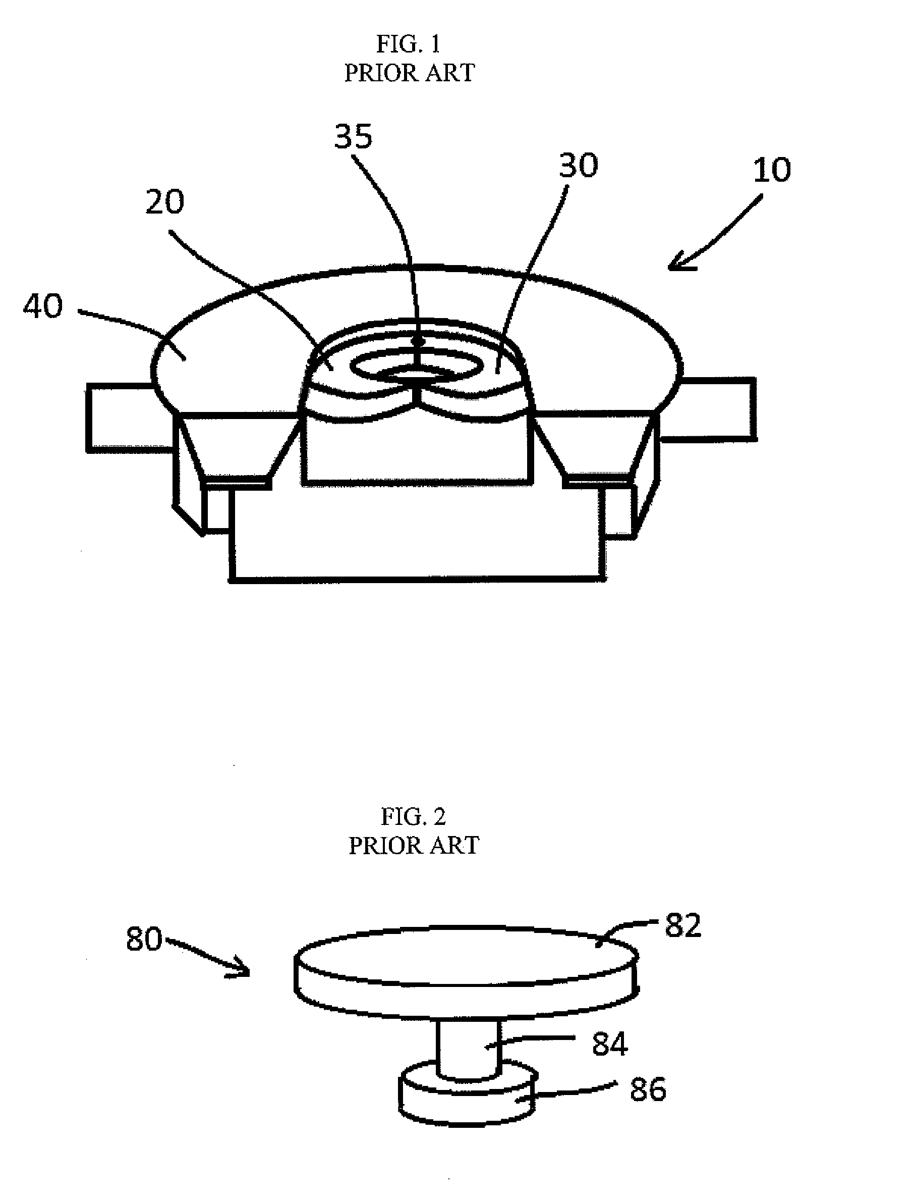
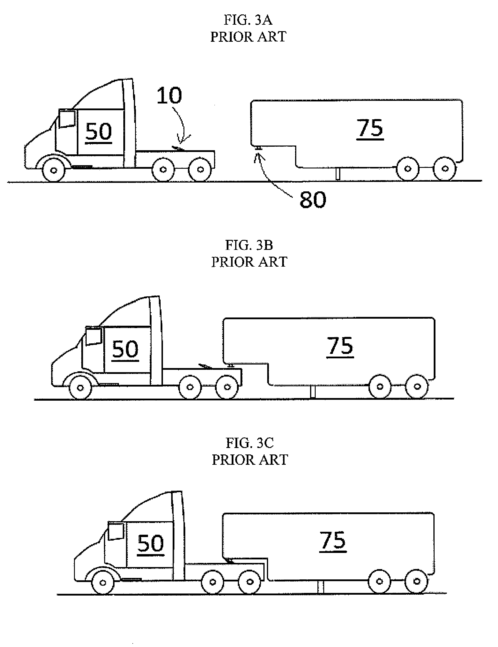
BACKGROUND[0001]1. Field[0002]Example embodiments relate to devices for restraining a vehicle, for example, a truck. The devices, for example, may attach to a fifth wheel that may be attached to the vehicle or which is part of the vehicle. The devices may be used, for example, to restrain a vehicle as the vehicle is undergoing a test. Example embodiments also relate to a method of testing a vehicle.[0003]2. Description of the Related Art[0004]FIG. 1 is a view of a “fifth wheel”10, a coupling structure commonly found on trucks. FIG. 2 is a view of kingpin 80, another coupling structure commonly found on trailers. The fifth wheel 10 serves as coupling structure to allow a trailer to attach to the truck via the kingpin 80. As shown in FIG. 1, the fifth wheel 10 includes a collar shaped member 40 which encloses a pair of jaws 20 and 30 coupled together by a pin 35. The kingpin 80 generally comprises an upper plate 82, a neck 84, and a lower flange 86. Typically, the jaws 20 and 30 of th...

Claims


Application Information

Patent Timeline
Patent Type & Authority Applications(United States)
IPC IPC(8): G01M17/007
CPCG01M17/007B62D53/08G01M17/0074
Inventor HEMERSON, ALBERT
Owner HEMERSON ALBERT
Learn More